


H
DMI Compliance & Sink Characterization Using DTG5000 Series Data Timing Generator
Application Note
6
www.tektronix.com/signal_sources
6
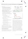
Intra-P
air Ske
w
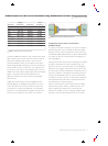
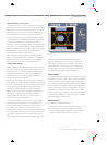
The Sink device also must tolerate a certain amount of
intra-pair skew, that is, timing skew (misalignment)
within respective differential TMDS pairs. The CTS
standar
d defines a limit of 0.4 x T
BIT
for intra-pair
skew tolerance.
The test starts by setting the clock and data pairs to
zero skew and then increasing the intra-pair skew in
steps of 0.1 x T
BIT
until the Sink device displays an
er
r
or
. The maximum skew setting that still pr
ovides
error-free Sink operation is defined as the intra-pair
skew; this r
esult is compar
ed against the published
limit. If the skew tolerance is greater than 0.4 x T
BIT
,
the device is considered compliant with the standard.
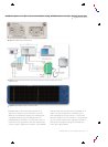
The DTG5000 Series uses its unique differential timing
of
fset capability in conjunction with 2 channels of a
differential DTGM30 module to fulfill this specific
test requirement.
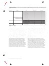
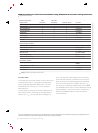
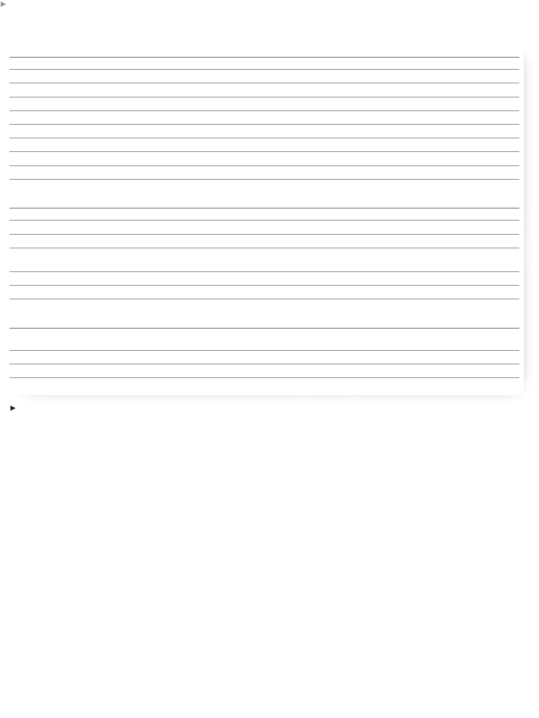
Sink Test Instrument Jitter Min. Diff.
Requirements Tolerance Sensitivity Intra-Pair Skew Remarks
Digital Storage Oscilloscope • • • 16M record length
Differential Probes • • • > 2 ea
TPA-R Test Adapter Set • • • 013-A012-50
TPA-P Test Adapter Set • • • 013-A013-50
12 SMA Cables • • • 174-1428-00
JAE Cable Emulator • 74.25, 27MHz
DC Power Supply • • • +5V
GPIB USB Controller • • • NI GPIB-USB-B
GPIB Cable • • •
Characterization Solution
Data Timing Generator • • • DTG5274 w/ 3 DTGM30 (Note
1
)
Arbitrary Waveform Generator • AWG710/B (Note
1
)
1) SMA-BNC adaptor • 015-1018-00
Cable from DTG DC O/P Pin-to-SMA • 012-1506-00 + 015-0671-00 +
at Bias Tee (2 nos.) 015-1018-00 (Note
1
)
SMA(m) - SMA(f) Cables (2) • (Note
1
)
Mini-Circuits Bias Tee (2 nos.) • ZFBT-4R2GW (Note
1
)
C
ompliance Solution
Data Timing Generator • • • DTG5274 w/ 3 DTGM30/ 1
DTGM32
Function Generator up to 10MHz • 2 channel AFG3022, 3102 or 3252
2) SMA-BNC adaptor • 015-1018-00
2) SMA Cables • 174-1428-00
Table 3.
Equipment for sink jitter tolerance tests.
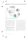
1
There are two recommended solutions for the Jitter Tolerance test; one for characterization and one for compliance. Using the AWG710B as the jitter generator allows for jitter profiles beyond compliance standards, which is
a
ppropria
te for characterizia
tion work.
Using the DTGM32 as the jitter genera
tor will enable testing up to the compliance specifica
tions.