


H
DMI Compliance & Sink Characterization Using DTG5000 Series Data Timing Generator
Application Note
8
www.tektronix.com/signal_sources
8
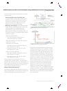
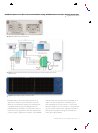
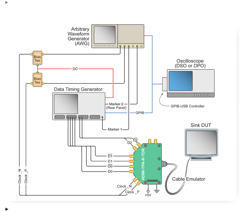
Jitter tolerance tests require a variable amount of jitter
to be imposed on signals being sent to the device
under test. The DTG5000 Series instruments are fully
compatible with either of two recommended jitter
solutions. One solution pairs the DTG5000 Series with
an arbitrary waveform generator for either compliance
or characterization work; the other, lower-cost solution
involves a jitter generator module plugged into the
DTG5000 Series mainframe and driven by an external
function generator. Both approaches provide the
necessar
y modulated jitter pr
ofiles for the generated
clock signal as follows:
–
Arbitrar
y
W
a
vef
orm Generator (AWG) Method:
This solution taps the full power of the DSO and
its TDSHT3 application softwar
e, the DTG5000
Series instr
ument, and the AWG.
The TDSHT3 softwar
e generates the specific jitter
modulation waveform and sends it to the AWG710B,
which in turn acts as the clock source for the jitter
tolerance test. The jitter is steadily increased by the
softwar
e until the device fails. The data lines ar
e
then verified by the oscilloscope for compliance.
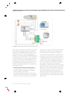
The A
WG has two digital “Marker” outputs that can
be used for synchronization, among other purposes.
In HDMI sink testing, one marker connects to the
DTG5000 Series exter
nal clock input while the second
marker connects to the DTG5000 Series trigger
input, both providing synchronization. Data signals
for the device under test are sourced by the
DTG5000 Series. Bias Tees are required to bring the
AWG710B out put's clock signals up to the required
TMDS levels. Conveniently
, these Bias T
ees can be
powered by the built-in DC output on the DTG5000
Series. The A
WG method is able to str
ess the
device beyond the compliance specification levels,
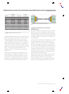
making it suitable for characterization work. Figure 5
illustrates the layout of a test configuration using the
A
WG method.
Figure 5.
Sink jitter tolerance test setup using an AWG as the jitter source.