Getting Started
PS280 & PS283 User Manual
5
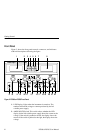
3. AMPS Indicator. Lights when AMPS is selected with the
AMPS/VOLTS switch for the left variable power supply.
4. VOLTS Indicator. Lights when VOLTS is selected with
AMPS/VOLTS switch for the left variable power supply.
5. AMPS Indicator. Lights when AMPS is selected with the
AMPS/VOLTS switch for the right variable power supply.
6. VOLTS Indicator. Lights when VOLTS is selected with
AMPS/VOLTS switch for the right variable power supply.
7. AMPS/VOLTS Switch. This switch selects whether the LED
display for the right variable power supply shows the current or
the voltage. If the switch is pushed to the left, the display shows
the current. If the switch is pushed to the right, the display shows
the voltage.
8. LED Display. Lights when the instrument is turned on. The
numbers indicate the voltage or current produced by the right
variable power supply.
9. POWER Button. Turns on the instrument when pressed. When
pressed again, it turns off the instrument.
10. CURRENT Knob. Use this control to set the output current for
the right, variable power supply. If the instrument is in a tracking
mode, the left power supply is the slave and the CURRENT
knob has no effect.
11. C.C. Indicator. If this is lighted, the left variable power supply is
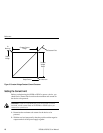
producing a constant current. See Figure 3 on page 10 for an
illustration of the constant voltage/constant current cross-
over point.
12. C.V. Indicator. If this is lighted, the left variable power supply is
producing a constant voltage. See Figure 3 on page 10 for an
illustration of the constant voltage/constant current cross-
over point.


