


Part No. TEL–09949, Rev A
June 2001
Pre-Installation Information and Activities
Page 12 of 34
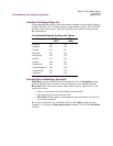
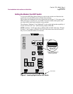
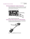
Setting the Modem Card DIP Switch
An 8-position DIP (Dual Inline Package) switch on the modem card functions the
same as the rear panel DIP switch on stand-alone modems.
The switches are numbered from left to right on the card (Figure 3). You must set the
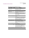
DIP switch before installing the card. Table 3 lists the switches and explains their
use. Open (Off) is the factory default for the switches.
The references “Modem A” and “Modem B” in refer to the dual modem capability of
models 3262 and 3267. See “A/B Switching and the A/B LED.”
NOTE: Switches 7 and 8 apply only to Models 3262 and 3267 (dial-only). Though
Switches 7 and 8 appear on Models 3263 and 3268 (leased line with dial restoral),
they are not connected and have no function.
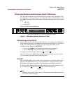
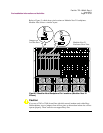
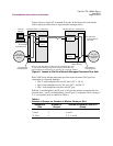
Figure 3. Locating Eight-Position DIP Switch
12345678
Front Panel
Switches 7 and 8
Apply to Models
3262 and 3267
(Dial Only)
The factory default for the
326X Series Modem
switch is open (off).