


Part No. TEL–09949, Rev A
June 2001
Pre-Installation Information and Activities
Page 19 of 34
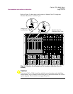
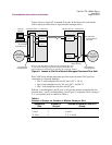
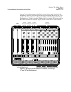
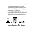
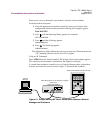
Figure 8 shows a single NC command flow path. In the figure, the local masters
receive network control from a single network manager source.
Figure 8. Leased or Dial Line Network Managed Command Flow Path
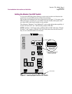
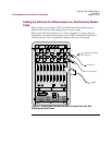
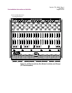
Each 326X Series Modem backplane provides network control (NC) ports for
connection to a Network Manager:
• The 21-card backplane has four NC ports (NC 1 - NC 4)
• The 9-card backplane has two NC ports (NC 1 and NC 2)
• The 1-card backplanes each have one NC port
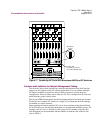
With the 1-card backplane, the NC port is only for the modem occupying that slot,
but with the 9-, and 21-card backplanes, one NC port is assigned to serve a group of
4, 5, or 6 modem cards as outlined in Table 4.
Remote
Slave
Local
Master
Network
Manager
For Any
Daisy-Chained
Device.
In-Connector
from Backplane:
Not Used.
In-Connector
from Backplane.
Remote
Master
Digital NC Bus
For Any
Daisy-Chained
Device.
Notes: (1) The dotted lines indicate the NC command flow path.
(2) The network manager regards all 326X Series Modems in a
group and their associated slaves as operating on a single NC channel.
Modular Nest 9 or 21 Enclosure
Modular Nest 9 or 21 Enclosure
Local
Slave
Out-Connector
from Backplane.
Out-Connector
from Backplane.
Backplane
Backplane
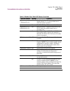
Table 4.
Number of Groups vs. Number of Modem Cards per Slot
Backplane
Size
Number of
Groups
Number of Modem Cards in a
Group
1 Card 1 1
9 Card 2 5 and 4
21 Card 4 5, 5, 5, and 6