


Part No. TEL–09949, Rev A
June 2001
Pre-Installation Information and Activities
Page 14 of 34
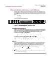
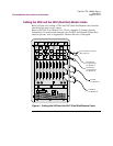
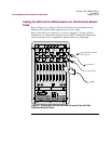
Cabling the 3262 and the 3267 (Dual Dial) Modem Cards
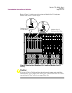
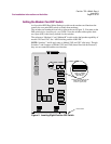
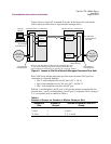
Refer to Figure 4 for cabling of 3262 and 3267 (dual dial) Modem cards. Interface
and cabling pin-outs vary by country.
Refer to the 326X Series Modem User’s Guide, Appendix C, Country-Specific
Information, for interface and cable pin-outs. For DTE and Network Control Port
interface pin-outs, refer to Appendix B, Interface Pin-outs, of that guide.
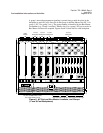
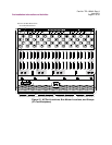
Figure 4. Cabling the 3262 and the 3267 (Dual Dial) Modem Cards
DIAL LINE A
2W LEASE
DIAL LINE B
2W/4W LEASE
OUT
NC
MSTR
2
COMM +5V +12V -12V
AC POWER
IN OUT
NC
MSTR
1
NC BUS
To Dial Line
or Leased Line
for Modem A
To Dial Line
or Leased Line
for Modem B
To DTE
for Modem A
To DTE B
for Modem B
A8 A6 A4 A2
A9 A7 A5 A3 A1
B8 B6 B4 B2
B9 B7 B5 B3 B1
SLOT98 765 432 1
AAAAAAAAA
DTE DTE DTE DTE DTE DTE DTE DTE DTE
BBBBBBBBB
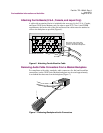
Ferrite bead (in countries
that require it)