


Part No. TEL–09949, Rev A
June 2001
Pre-Installation Information and Activities
Page 13 of 34
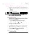
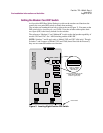
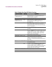
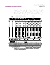
Table 3. Modem Rear Panel DIP Switch Functions
Switch Number Setting Function
1 (Modem A only)
7 (Modem B only)
Off EIA/TIA 232-D pin 23 is set for data rate input.
Setting Switch 1 or 7 to this position has no
effect on modem operation.
On EIA/TIA 232-D pin 23 is set as a data indicator.
2 (Modem A only)
8 (Modem B only)
Off Busy Out Select. A signal on EIA/TIA 232-D
Pin 25 makes the modem appear busy to
incoming calls.
On Test Indicator Signal (V.24 Circuit 142) Select.
The modem sends a signal to the terminal on
EIA/TIA 232-D Pin 25 (V.24 Circuit 142) when
a test is in progress.
3 (Modems A and B) Off Front panel enable. The front panel functions
normally.
On Front panel disable. You can check only status
displays. NOTE: If your modem is under remote
configuration control by another 326XSeries
Modem, the controlling modem retains front-
panel control of your modem.
4 (Modems A and B) Off Normal password protection applies.
On This reinitializes the modem to its factory
settings. Use this when you forget your
password, to unlock the modem from password
protection.
5 (Modems A and B) Off AT and V.25 bis command sets can be used from
an attached terminal.
On AT and V.25 bis command sets cannot be used
from an attached terminal. NOTE: If your
modem is under remote configuration control by
another 326X Series Modem, the controlling
modem retains AT ACU control.
6 (Modems A and B) Off Factory use only.