I/O Connectors and Signals
3-8
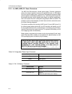
3.3.3 J6, JMP5, JMP6, B1: Power Connectors
The MSC1211EVM features a flexible power supply. Externally generated
power, the onboard regulator circuitry and supplied wall-wart, or a 9V battery
can all be used to supply power. Furthermore, the separated analog and digital
power supplies can be powered differently; e.g., the analog power supply can
be powered externally, and the digital power supply can use the onboard regu-
lator, at the same time; this is configured using jumpers JMP5 and JMP6. The
exception to this is that the battery and wall–wart cannot be used at the same
time (see following paragraph).
Four power connectors are provided: JMP5 (pins 2–3) and JMP6 (pins 2–3)
for external power, battery terminal B1 for a 9V transistor radio battery, and J6
for the supplied wall-wart. J6 is a switched jack—connecting a plug to J6 auto-
matically disconnects the battery terminal. This prevents the battery and J6
from supplying power simultaneously.
Battery power is regulated by the same circuitry that regulates J6 (wall–wart)
power. Note that when a battery is connected to B1, approximately one half
of the prototyping area is covered up by the battery.
Caution: Be very careful when connecting external power supplies
to JMP5 (pins 2 and 3) and JMP6 (pins 2 and 3). They are not
protected against reversed polarity. If you connect them
backwards (i.e., with reversed polarity), it is likely that the
MSC1211EVM will be permanently damaged.
Table 3–6.Unregulated Power Input Connector
Terminal name Function
Tip Positive power supply input
Sleeve Power ground
Table 3–7.B1: 9V Battery Connector
Terminal name Function
Split (female) ring Positive
(mates with solid/male post on battery)
Solid (male) ring Negative
(mates with split/female post on battery)


