


I/O Connectors and Signals
3-10
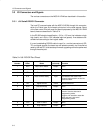
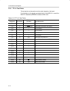
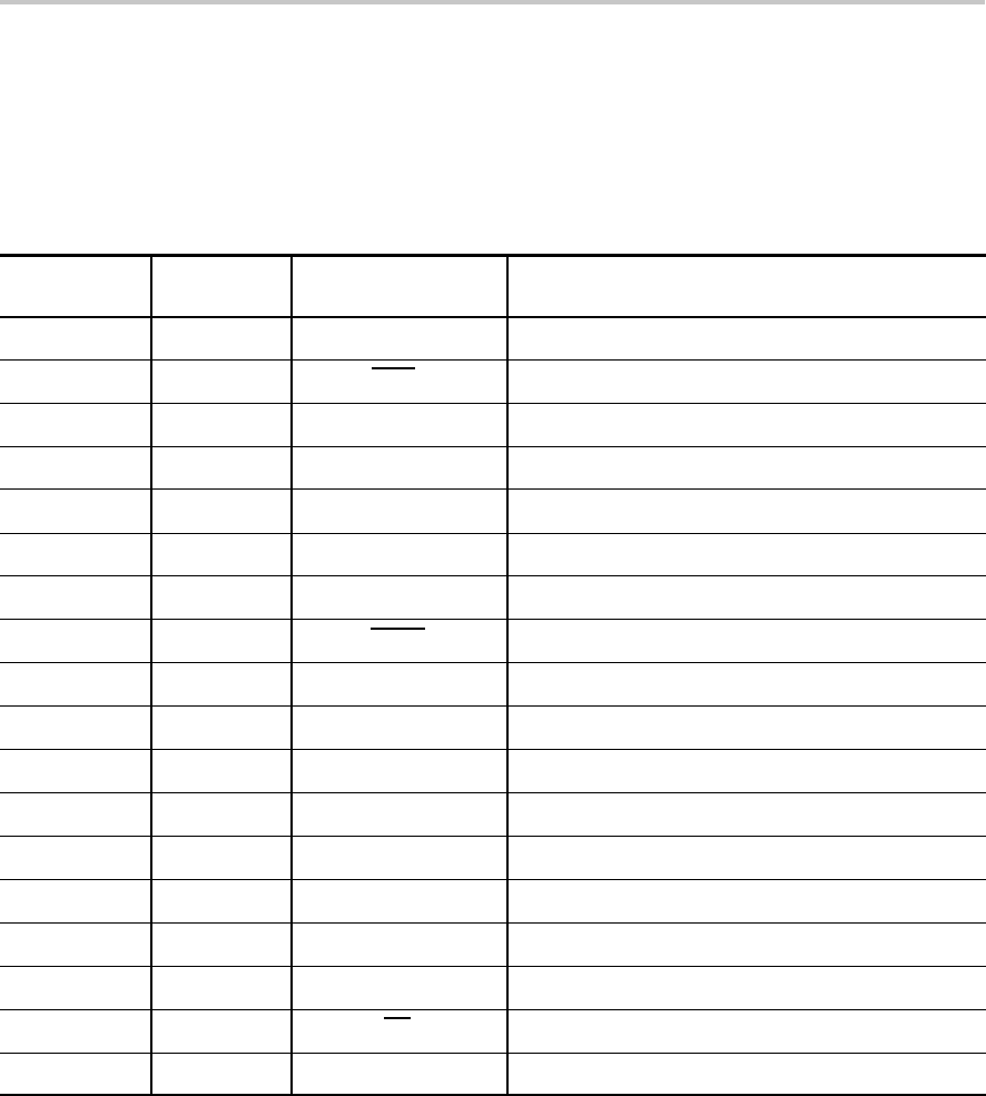
3.3.6 TP1–6: Test Points
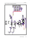
The test points can be used to monitor certain signals on the board.
For information on the signals connected directly to the MSC1211, consult the
MSC1211 datasheet (SBAS267) located at www.ti.com.
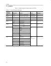
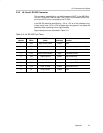
Table 3–10.TP1–6: Test Points
Test Point
Designator
MSC1211
Pin Number
MSC1211
Pin Name
Signal Description
TP1 — — GND
TP3 6 P3.3/INT1/PWM PWM output connected to the speaker
TP4 — — RTS on Serial0
TP5 — — DTR on Serial0
TP6 — — RX on Serial0
TP7 — — TX on Serial0
TP8 13 RST Reset signal to the MSC1211
TP9 44 PSEN Program Select Enable from MSC1211
TP10 — — A0
TP11 — — A1
TP12 — — A2
TP13 — — A3
TP14 — — A4
TP15 — — A5
TP16 — — A6
TP17 — — A7
TP18 48 EA External Memory Enable
TP19 45 ALE Address Latch Enable