


6.8.5ControlRegister5Tab
6.8.6ControlRegister6Tab
KitOperation
www.ti.com
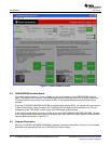
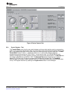
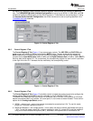
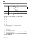
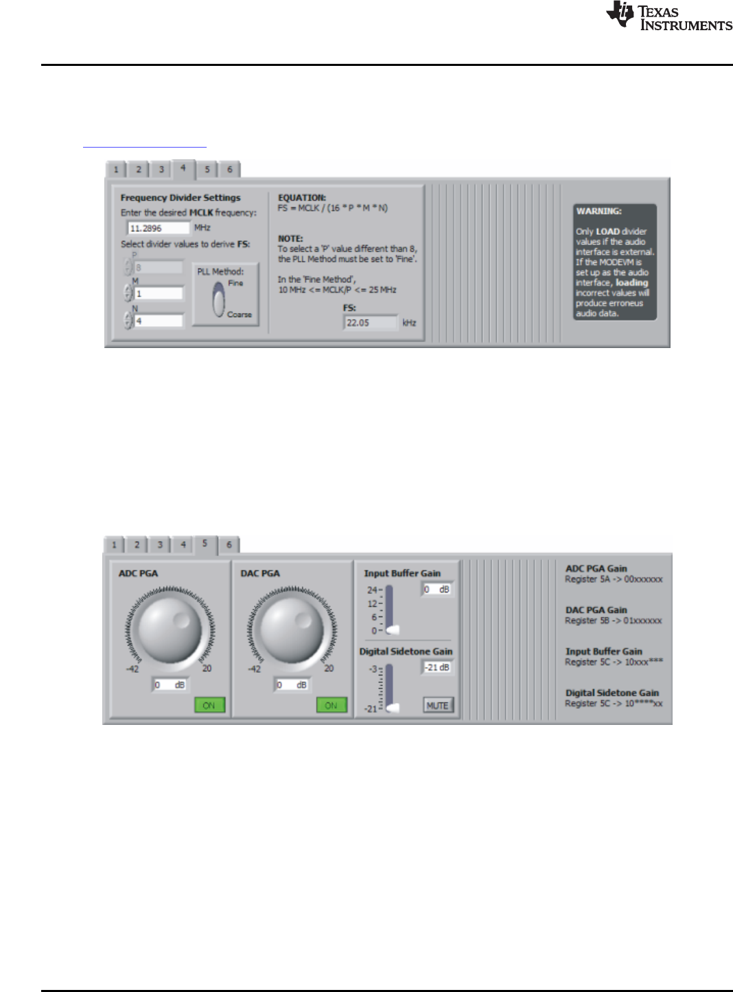
aremerelyforillustration;whatisactuallywrittentoregisters4Aand4BarethevaluesofP,MandN
only.TheUSB-MODEVMAudioInterfaceConfigurationissetupforanMCLK=11.2896MHz,soP,M
andNmustsatisfytheFSequationandtheSCLKequationinTurboModeforthatconfiguration.Ifusing
theExternalAudioInterfaceConfiguration,thedividervaluescanbesettoanythingspecifiedinthe
TLV320AIC12K/14Kdatasheet.
Figure10.ControlRegister4Tab
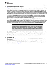
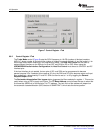
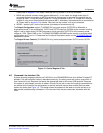
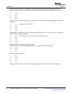
TheControlRegister5Tab(Figure11)hasseveralgaincontrols.TheADCPGAandDACPGAgain
knobsrangefrom-42dBto20dBandeachhaveaMUTEbutton.Thegainknobsandtherespective
MUTEbuttonswritetoregister5AfortheADCPGAandtoregister5BfortheDACPGA.Slidersare
providedfortheInputBufferGain(0dBto24dB)andtheDigitalSidetoneGain(-21dBto-3dBw/MUTE)
andtheybothshareregister5C.Forconvenience,thecorrespondingregisterforeachcontrolisprovided
totherightofthetab.An'x'denotesthebitsmodifiedbythecorrespondingcontrol.
Figure11.ControlRegister5Tab
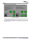
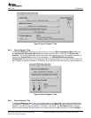
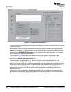
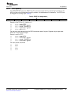
TheControlRegister6Tab(Figure12)providescontrolstoselecttheanaloginputandtoconfigurethe
analogoutputs.NotethatOUTP2/P3areonlyavailableontheTLV320AIC12/12K.The
TLV320AIC12KEVMB/14KEVMBprovidesa1/8"audiojack(J8)toconnectamicrophone,anon-board
electretmicrophone(MK1)andanother1/8"audiojack(J11)toconnectastereoheadset.Therearefour
optionsfortheAnalogInputSelectcontrol:
a.INP/M1-selectsinput1astheinputsource(connectedtoscrewterminalJ10).Tousethismode,
jumperW11mustbeinstalledonpins2-3.
b.MICINself-biasedto1.35V(single-ended)-Inthismode,thedeviceinternallyself-biasestheinputto
1.35V.Tousethismode,jumperW11mustbeinstalledonpins2-3.JumperW12mustbeinstalledif
usingtheon-boardelectretmicrophone(MK1),otherwiseamicrophonecanbeconnectedtoJ8.
18TLV320AIC12KEVMB-KandTLV320AIC14KEVMB-KUser'sGuideSLAU229B–October2007–RevisedAugust2008
SubmitDocumentationFeedback