


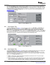
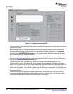
6.9CommandLineInterfaceTab
www.ti.com
KitOperation
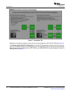
PleaserefertoAppendixAfordetails.NotethattheringcontactinJ8isnotconnected.
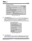
c.MICINwithexternalcommonmode(pseudo-differential)-Inthismode,thesingleendedinputis
connectedthroughac-couplingtoMICINandthebiasvoltageusedtogeneratethesignalisalsoac
coupledtoINM1.Tousethismode,jumperW11mustbeinstalledonpins1-2.JumperW12mustbe
installedifusingtheon-boardelectretmicrophone(MK1),otherwiseamicrophonecanbeconnectedto
J8.PleaserefertoAppendixAfordetails.NotethattheringcontactinJ8isnotconnected.
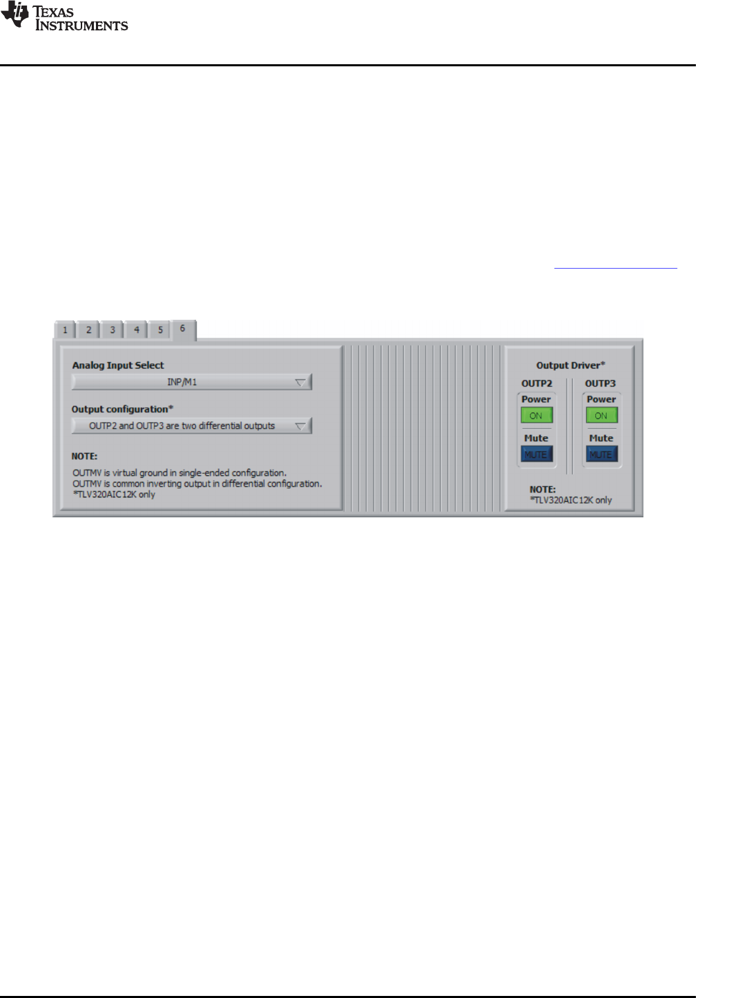
d.INP/M2-selectsinput2astheinputsource(connectedtoscrewterminalJ9).
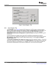
TheOutputConfigurationcontrol(TLV320AIC12Konly)setsoutputsOUTP2/P3todifferentialor
single-endedmode.Ifsettodifferential,OUTP2andOUTP3sharepinOUTMVasthecommoninverting
output.Ifsettosingle-ended,OUTMVbecomesavirtualgroundforOUTP2/P3atthecommonmode
voltageof1.35V.SwitchSW2ontheTLV320AIC12KEVMB/14KEVMBcanbeusedtotrymultipleoutput
configurationsonJ7andJ11.PleaseseetheFunctionalDescriptionsectionontheTLV320AIC12K/14K
datasheetfordetails.
TheOutputDriversControls(TLV320AIC12Konly)mutesandpowersdownOUTP2and/orOUTP3.
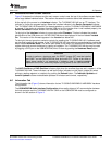
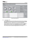
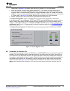
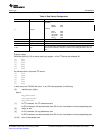
Figure12.ControlRegister6Tab
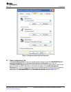
AsimplescriptinglanguagecontrolstheTAS1020ontheUSB-MODEVMfromtheLabView™-basedPC
software.Themainprogramcontrols,describedpreviously,donothingmorethanwriteascriptwhichis
thenhandedofftoaninterpreterthatsendstheappropriatedatatothecorrectUSBendpoint.Because
thissystemisscript-based,provisionismadeinthistabfortheusertoviewthescriptingcommandsthat
arecreatedasthecontrolsaremanipulated,aswellasloadandexecuteotherscriptsthathavebeen
writtenandsaved(seeFigure13).Thisdesignallowsthesoftwaretobeusedasaquicktesttoolorto
helpprovidetroubleshootinginformationintherareeventthattheuserencountersaproblemwiththis
EVM.
SLAU229B–October2007–RevisedAugust2008TLV320AIC12KEVMB-KandTLV320AIC14KEVMB-KUser'sGuide19
SubmitDocumentationFeedback