


www.ti.com
2.5VLYNQFunctionalDescription
Address
translation
commands
Outbound
Outbound
command
FIFO
data
Return
FIFO
data
FIFO
Return
command
Inbound
FIFO
Registers
translation
Address
TxSM
8B/10B
encoding
Serializer
commands
Inbound
RxSM Deserializer
decoding
8B/10B
Serial
TxData
Serial
TxClk
Serial
RxClk
Serial
RxData
Master
configbus
interface
Systemclock VLYNQclock
Slave
configbus
interface
(FIFO3)
(FIFO2)
(FIFO0)
(FIFO1)
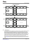
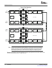
2.5.1WriteOperations
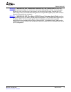
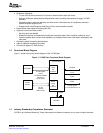
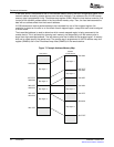
PeripheralArchitecture
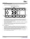
TheVLYNQcoresupportsbothhost-to-peripheralandpeer-to-peercommunicationmodelsandis
symmetrical.TheVLYNQmodulestructureisshowninFigure4.
Figure4.VLYNQModuleStructure
TheVLYNQcoremoduleimplementstwo32-bitconfigurationbusinterfaces.Transmitoperationsand
controlregisteraccessrequiretheslaveconfigurationbusinterface.Themasterconfigurationbus
interfaceisrequiredforreceiveoperations.Convertingtoandfromthe32-bitbustotheexternalserial
interfacerequiresserializeranddeserializerblocks.
8b/10bblockcodingencodesdataontheserialinterface.Framedelineation,initialization,andflowcontrol
usespecialoverheadcodegroups.
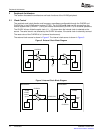
FIFOsbuffertheentireburstonthebusformaximumperformance,thusminimizingbuslatency.Using
writeoperationsofeachVLYNQmoduleinterfacedistypicallyrecommendedtoensurethebest
performanceonbothdirectionsofthelink.
Writerequeststhatinitiatefromtheslaveconfigurationbusinterfaceofthelocaldevicewritetothe
outboundcommand(CMD)FIFO.DataissubsequentlyreadfromtheFIFOandencapsulatedinawrite
requestpacket.Theaddressistranslated,andthepacketisencodedandserializedbeforebeing
transmittedtoremotedevice.Theremotedevicesubsequentlydeserializesanddecodesthereceivedata
andwritesitintotheinboundCMDFIFO.Awriteoperationinitiatesontheremotedevice’smaster
configurationbusinterfaceafterreadingtheaddressanddatafromtheFIFO.
ThedataflowbetweentwoVLYNQsthatareconnectedisshowninFigure5.Intheexampleshownin
Figure5,thewriteoriginatesfromthedevice.
14VLYNQPortSPRUF89–October2007
SubmitDocumentationFeedback