


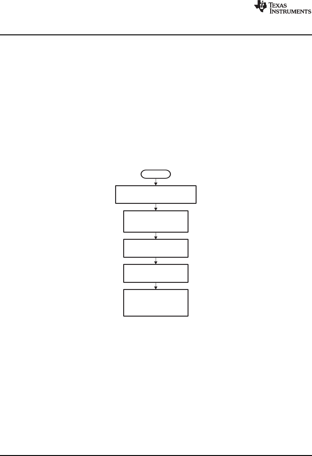
Reset
ProgramCNTHI,CNTLO,PRDHI,
PRDLO,TDDRHI,andPSCHI
ProgramWDTCR
parameters,
asrequired
SetWDENbit,
asrequired
ProgramENAMODEbits,
asrequired
,
ProgramWDKEY bits
toactivatethe
watchdogtimer,
ifnecessary
Timer Operation
www.ti.com
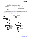
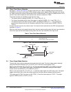
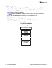
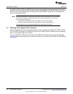
3.10 Initializing the Timer
After a hardware reset, the enabling mode (ENAMODE) bits in the timer control register (TCR) are cleared
to 0 and the timer is disabled. The timer counter and period registers are cleared to 0. The timer can be
configured to the desired mode by programming the control registers, TCR and (in the case of the
watchdog timer mode) WDTCR.
Figure 10 shows a typical timer initialization:
1. Write the timer counter and period values to CNTHI and/or CNTLO, and PRDHI and/or PRDLO
registers.
2. If the 4-bit prescaler is used, write the values to the TDDRHI and PSCHI bits.
3. Set the remaining control bits to the required state.
4. Set WDEN = 1 to use the timer as watchdog timer, if necessary.
5. To start the timer, set the ENAMODE bits to use the timer as a continuous interrupt generator
(ENAMODE bits = 10b) or as a one-time counter (ENAMODE bits = 01b).
6. Program the WDKEY bits, if the watchdog timer mode is selected.
Figure 10. Timer Initialization
18
C6472/TCI648x 64-Bit Timer SPRU818B–December 2005–Revised September 2010
Submit Documentation Feedback
Copyright © 2005–2010, Texas Instruments Incorporated