


Bill of Materials
2-4
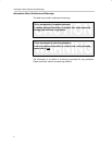
Warning
Users must not activate the load on SW_OUT before the SW_PG
rises to high, if the load current is higher than 50 mA. Otherwise,
the power switch output could not be charged up to SW_IN rail.
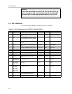
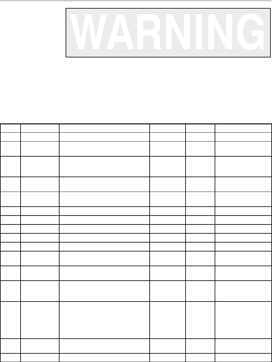
2.2 Bill of Materials
The bill of materials (BOM) for the EVM is shown in Table 2–1.
Table 2–1.Bill of Materials of the TPS2151 EVM (SLVP202)
Count RefDes Description Size MFR Part Number
3 C1, C3, C6 Capacitor, Tantalum, 4 µF, 10 V, 20% B Case Panasonic 29D475X0010B2T
4 C2, C4, C5, C8 Capacitor, ceramic 0.1 µF, 50 V, X7R
10%
805 Kemet C0805C104KRAC7800
0 C7 Note: Needed only if the LDO voltage
is set to be below 3 V, refer to the data
sheet
0 C9 Note: Extra high-value capacitor on
SW_OUT
2 J1, J2 Header, 8 pin, 100 mil spacing, (36-pin
strip)
0.100 x 8” Sullins PTC36SAAN
0 J3 Connector, USB downstream (Type A) 0.52 x 0.57” Molex 87531–001
3 JP1, JP4, JP5 Header, 2 pin, 100 mil spacing 0.100 x 2” Sullins PTC36SAAN
2 JP2, JP3 Header, 3 pin, 100 mil spacing 0.100 x 3” Sullins PTC36SAAN
2 R1, R3 Resistor, chip, 200 KΩ, 1/10 W, 5% 805 Std Std
1 R2 Resistor, chip, 625 kΩ, 1/10 W, 5% 805 Std Std
2 S1, S2 Switch, 1P2T, slide, PC-mount,
200 mA
0.46 x 0.16” E_Switch EG1218
5 TP1, TP2,
TP3, TP4, TP9
Test point, black, 1 mm 0.038” Farnell 240–333
0 TP16, TP17,
TP18, TP19,
TP20, TP21
Post, wire wrap, 0.043 press-fit
Note: A/A
0.015–0.025”
pins
Mill-Max 1045–3–17–15–30–14–
02–0
11 TP5, TP6,
TP7, TP8,
TP10, TP11,
TP12, TP13,
TP14, TP15,
TP22
Test point, red, 1 mm 0.038”, Farnell 240–345
0 TR1 Note: Paralleling with R2 to set LDO
output voltage lower than 3.3 V
1 U1 IC, USB high powered, with LDO PWP14 TI TPS2151PWP