


Layout of the EVM
2-5
Schematic, Bill of Materials, Layout, and Setup
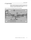
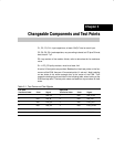
2.3 Layout of the EVM
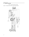
Figure 2–2 illustrates the placement of the components on the top-layer of the
TPS2151 EVM. All the components are placed on the top layer only. The
bottom layer is mainly a ground plane except for a few short traces. The center
rectangle box includes all the essential parts for the EVM.
Figure 2–2. Top Layer of the EVM and Placement of the Components