


1-1
Introduction
Each device in TPS2140/41/50/51 family integrates a dual-current-limiting
power switch and an adjustable low dropout regulator (LDO). Both the switch
and LDO limit inrush current by controlling the turnon slew rate and are
compatible with USB 1.0 and 2.0 Specifications.
The power switch has a unique dual-current-limiting function that limits the
current delivered to its load to less than 100 mA during power on. This feature
allows the load to utilize high-value capacitance at the output of the switch,
while keeping the inrush current low. When the output voltage from the switch
reaches about 93% of the input voltage, the switch power good output goes
high, and the switch current limit increases to 800 mA (minimum), at which
point higher current loads can be turned on. Therefore the load, other than
capacitance, on the switch output must not exceed the lower current limit (50
mA minimum) before the power good output rises to high.
Designers may activate the load by using either the power good signal or
another logic signal. The higher current limit provides short circuit protection
while allowing the load to draw maximum current from the source.
The switch and LDO function independently provides flexibility in many
applications requiring separate core and I/O voltages.
TPS2151 has a 5-V switch and an active high /SW_EN that distinguishes itself
from the other three parts (TPS2140, TPS2141, and TPS2150). For a detailed
description of functions and characteristics of the TPS2140/41/50/51, refer to
the data sheet (literature number SLVS399). You may check the data sheet
and ordering information on the Web site:
http://focus.ti.com/docs/prod/productfolder.jhtml?genericPartNumber=
TPS2151
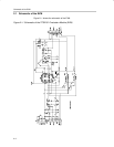
To assist designers in the evaluation of the device, an evaluation module
(SLVP202) is offered based on TPS2151. The EVM requires 5-V supplies for
both the power switch and the LDO. The LDO output voltage is set to 3.3 V by
an external resistor divider. Two slide switches and few jumpers on the EVM
are provided to change the connections between the LDO and the power
switch, so several different application configurations can be evaluated.
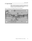
The required external parts for the EVM are two input capacitors (on SW_IN
and LDO_IN), three output capacitors (on SW_OUT and LDO_OUT), and a
resistor divider (two resistors). All of these components are placed inside a
white-rectangle box on the EVM.
Chapter 1