


Introduction
www.ti.com
1 Introduction
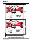
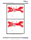
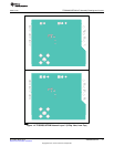
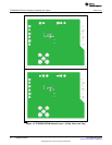
The TPS62065-67EVM-347 is a fully assembled and tested pair of PCBs for evaluating the TPS62065
and TPS62067 2-A step-down converters. The EVM comes configured with both a TPS62065 IC and a
TPS62067 IC; there are two PCBs, one for each respective step-down converter IC.
1.1 Features
• Input voltage range: 3.0 V to 6.0 V
• Adjustable output voltage: 0.8 V to VIN
• Up to 2.0-A output current
• 3-MHz switching frequency
• Power Good output (TPS62067EVM only)
• Clock dithering
1.2 TPS62065/67 Applications
The TPS62065 and TPS62067 step-down converters are ideal for these applications:
• POL
• Digital cameras
• PDAs, pocket PCs
• Portable media players
• DSP supply
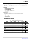
2 Electrical Performance Specifications
Table 1 summarizes the TPS62065/67EVM performance specifications.
Table 1. TPS62065/67EVM Performance Characteristics
Notes and
Parameter Symbol Conditions Min Typ Max Units
Input Characteristics
Input Voltage VIN 3.0 6.0 V
Falling 1.73 1.78 1.83 V
Input Undervoltage Lockout
V
IN_UVLO
(UVLO)
Rising 1.9 1.95 1.98 V
Output Characteristics
Line Regulation 0 %/V
Load Regulation –0.5 %/A
Output Current 1 I
OUT
1 VIN = 3.0 V to 6.0 V 2000 mA
Forward Current Limit
High-Side and Low Side I
LIMF
VIN = 3.0 V to 6.0 V 2300 2750 3300 mA
MOSFET
Systems Characteristics
Switching Frequency f
SW
2600 3000 3400 kHz
Peak Efficiency h
pk
VIN =Nom 95 %
VIN = 5.0 V, VIN =
Full Load Efficiency h 1.8 V I
OUT
= 2,000 82 %
mA
2
TPS62065/67EVM SLVU364–March 2010
Submit Documentation Feedback
Copyright © 2010, Texas Instruments Incorporated