100
95
90
85
80
75
70
65
60
55
50
0 0.2 0.4 0.6 0.8 1.0 1.2 1.4 1.6 1.8 2.0
I (A)
OUT
Efficiency(%)
V =3.0V
IN
V =3.3V
V =3.6V
V =4.2V
V =5.0V
IN
IN
IN
IN
L=1.0 H(LQH441R0)
C =10 F(0603size)
m
m
OUT
V =1.8V
Mode:AutoPFM/PWM
OUT
EFFICIENCYvsLOADCURRENT
2V/div
500mA/div
2A/div
1V/div
500mA/div
Time(100 s/div)m
V =3.6V
V =1.8V
Load=R2R
IN
OUT
L=1.2 H
C =10 F
m
m
OUT
TPS62065Startup
TPS62065/67EVM Test Data
www.ti.com
6 TPS62065/67EVM Test Data
Figure 4 through Figure 11 present typical performance curves for the TPS62065/67EVM. Actual
performance data can be affected by measurement techniques and environmental variables; therefore,
these curves are presented for reference and may differ from actual results obtained by some users.
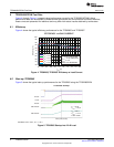
6.1 Efficiency
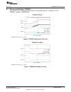
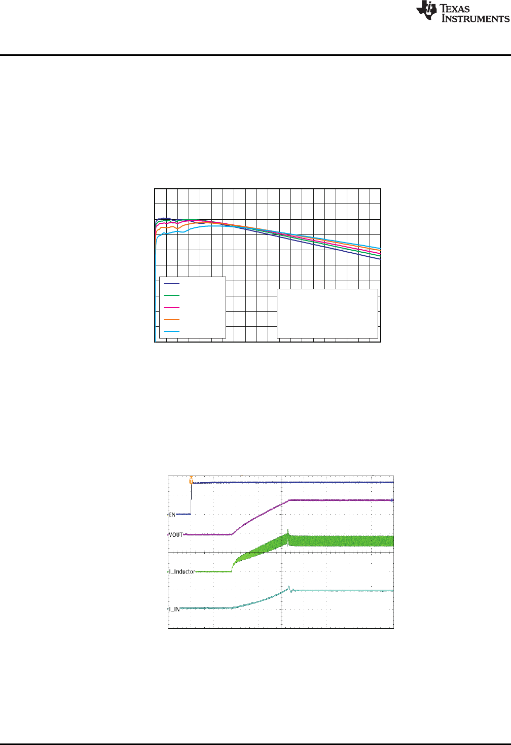
Figure 4 shows the typical efficiency performance for the TPS62065 and TPS62067.
Figure 4. TPS62065, TPS62067 Efficiency vs Load Current
6.2 Start-up: TPS62065
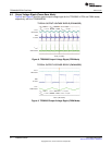
Figure 5 shows the typical start-up performance for the TPS62065 using the TPS62065EVM.
Conditions: VIN = 3.6 V, V
OUT
= 1.8 V
Figure 5. TPS62065 Startup into 2.2-Ω Load
8
TPS62065/67EVM SLVU364–March 2010
Submit Documentation Feedback
Copyright © 2010, Texas Instruments Incorporated


