


J12
J13
J11
J14
J10
J15
JP10
ON
EN
OFF
VIN
GND
VOUT
GND
S+
+
S+
S-
-
S-
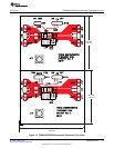
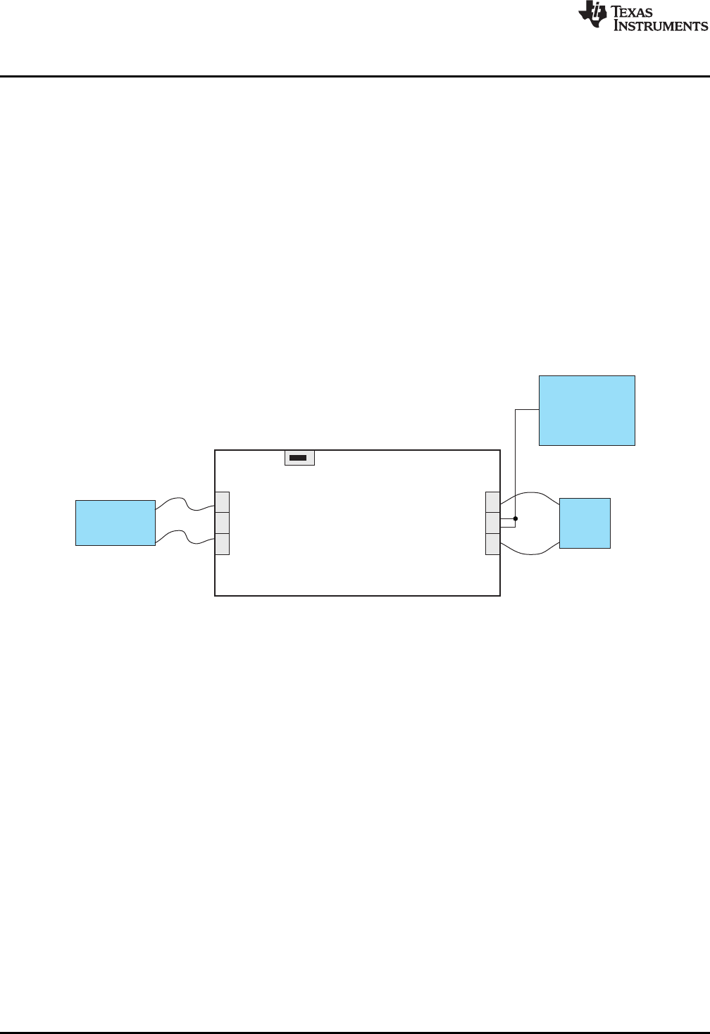
TPS62065/67EVM-347
DC
PowerSupply
Load
Oscilloscope
Test Configuration
www.ti.com
4.2.8 JP20 EN
This jumper enables/disables the TPS62067 device on the EVM. Shorting jumper JP20 between the
center pin and On turns on the unit. Shorting the jumper between center pin and Off turns the unit off. A
1-MΩ pull-up resistor is connected between VIN and EN. Removing jumper JP20 also turns on the
converter.
4.2.9 J27 VOUT (SMA)
This SMA connector is connected to the output voltage of the TPS62067. It can be used to easily analyze
the noise spectrum of the output voltage with a spectrum analyzer. By default, J27 is not assembled on
the EVM.
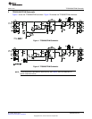
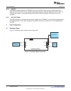
5 Test Configuration
5.1 Hardware Setup
Figure 3 illustrates a typical hardware test configuration.
Figure 3. Hardware Board Connection
6
TPS62065/67EVM SLVU364–March 2010
Submit Documentation Feedback
Copyright © 2010, Texas Instruments Incorporated