


26 Gecko Frames Instruction Manual
Section 2 — Installation
Module Installation
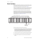
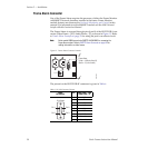
There are ten cell locations in each frame to accommodate either video or
audio modules (module types cannot be mixed in a frame). These are the
ten cells located on the left side of the frame. Refer to Figure 8.
Modules can be configured for up to eight outputs. The 8500 modules have
six outputs. The 8800 and 8900 modules have eight outputs. Refer to indi-
vidual module manuals for input/output configuration information.
The two cells on the right are allocated for the power supplies only.
The third cell from the right, is allocated only for the Frame Monitor or
8900NET Network Interface module. This module provides the interface
for the forced-air cover, as well as the Frame Alarm reporting. For addi-
tional information concerning the Frame Monitor and Network Interface
modules, refer to Section 4-Monitoring and Control.
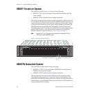
Figure 8. Gecko 8900 Series Frame
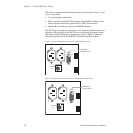
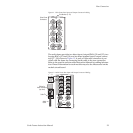
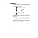
To install a module into the frame, follow these steps:
1. Insert the module into the frame, connector-end first, with component
side of the module facing to the right with the ejector tab at the top. The
Frame Monitor and the 8900NET module have a connector tab with a
circular finger-hole for pulling the module rather than an ejector tab.
The connector tab should be oriented in the top half of the frame.
2. Verify that the module connector seats properly against the backplane.
3. Press the ejector tab or connector tab in to seat the module in place.
4. Install a module template overlay from the Instruction Manual if
present.
Any 8900 Module
Power
Supplies
(only)
0636-04r2
Frame Monitor or
8900NET Network
Interface Module