


30 Gecko Frames Instruction Manual
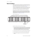
Section 2 — Installation
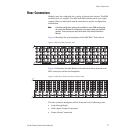
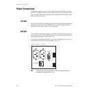
Frame Alarm Connector
Use of the Frame Alarm requires the presence of either the Frame Monitor
or 8900NET Network Interface module in the frame. Frame Monitor
module features are discussed in Section 4-Monitoring and Control in this
manual. For information on the 8900NET module see the 8900 Network
Interface Module Instruction Manual.
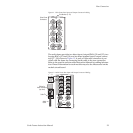
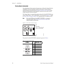
The Frame Alarm is accessed through pins 8 and 9 of the RS-232 DB-9 con-
nector (Video Frame – J102, Audio Frame – J7) as shown in Figure 13. Refer
to Frame Alarm Example on page 32 for using the port in an alarm circuit.
Note Earlier model 8900 frames had a SMPTE ALARM BNC for accessing the
Frame Alarm output. Refer to SMPTE Alarm Connector on page 46 for
cabling information on older frames.
Figure 13. Frame Alarm Connector Location
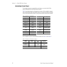
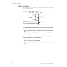
The pinout for the RS-232 DB-9F connector is given in Table 6.
Table 6. RS-232 Connector Pinouts
Frame
RS-232 Port
Pin
Video Frame – J102
Audio Frame – J7
1 N/C
2TX
3RX
4 N/C
5 Gnd
6 N/C
7 N/C
8 Frame Alarm
9 Frame Alarm
J1 J2
RS232
ETHERNET
Frame Alarm
(Video – J102 pins 8 and 9)
(Audio – J7 pins 8 and 9)
0636 -20r0
Pin 5
Pin 6
Pin 9
D-9 Female
Pin 1