


32 Gecko Frames Instruction Manual
Section 2 — Installation
Frame Alarm Example
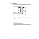
Refer to Figure 14 for an example of a typical alarm schematic using pins 8
and 9 of the RS-232 port.
Figure 14. Typical Alarm Schematic for Frame Alarm
The impedance between the pins 8 and 9 of the RS-232 connector can be in
one of two states:
•Open – less than 100 µA of current will flow with 5 volts across the pins,
and
•Closed – less than 0.2 V will appear from pin 8 to pin 9 with 20 mA of
current flowing.
There are three operational conditions (capability is module dependent,
refer to specific module instruction manual):
•Open – no faults,
•Closed – there is an internal fault, and
• Pulsing – there is a missing or invalid signal on one or more of the mod-
ules.
+5V
4.7 kΩ
4.7 kΩ
330 Ω
470 Ω
Alarm
LED
2N4126
(or equivalent)
RS-232 Pin 8
RS-232 Pin 9