36
G8000 Series Installation and Operation Manual
11.4 External Breakers
The G8000 UPS units are not equipped with circuit breakers. Qualied personnel should provide the
external breakers for the AC input/output, bypass input and DC input.
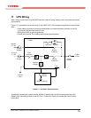
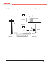
See Figure 11.1 – External Wiring Diagram, for the circuit position of the breakers.
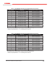
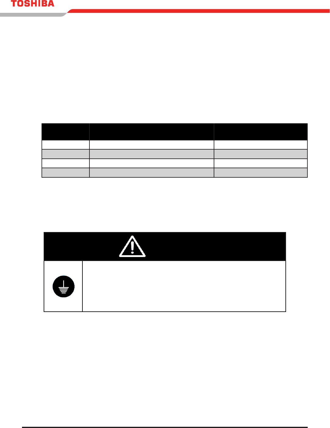
Table 11.6 shows the G8000 UPS minimum external breaker rating for each capacity. The bypass input and
the AC output require 3-pole breakers.
TABLE 11.6 EXTERNAL BREAKER RATING
Capacity
AC Input / Bypass Input / AC Output
Minimum Breaker Rating
DC Input
Minimum Breaker Rating
100 kVA 480 V - 200 A 500 VDC – 500 A
150 kVA 480 V - 300 A 500 VDC – 700 A
225 kVA 480 V - 450 A 500 VDC – 1100 A
300 kVA 480 V - 500 A 500 VDC – 1500 A
11.5 Grounding Wire
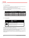
WARNING
Be sure to ground the UPS as specied.
Using the UPS without a proper ground will deteriorate the insulation,
cause leakage of currents and electric shock.The resistance to ground
should be less than or equal to 10 ohms.
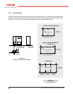
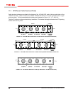
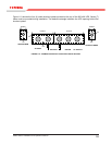
The 100/150/225kVA earth grounding bus is located inside, at the bottom-front of the unit. The 300 kVA
earth grounding bus is located inside, at the top-left of the unit.
Use a AWG 2 (or 38 mm
2
) or larger cable for the grounding wire. Run the grounding wire through the
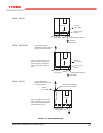
opening at the bottom, or through a hole in the top knockout plate (if available). See Figure 11.10. Connect
either the top or bottom earth ground bus, but not both, to the grounding wire.
The ground wire must have a crimp terminal with a 1/2 in. (12 mm) diameter bolt hole. The ground bus has
33/64 in. (13 mm) bolt hole. The connect the crimp terminal and ground bus together using a 7/16 in. (10
mm) diameter bolt.


