


40
G8000 Series Installation and Operation Manual
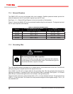
11.7 Grounding Conguration
This section describes the grounding conguration to be used with various AC service entrance congurations.
Inadequate grounding will cause problems at start-up. Connections for the ground line and the neutral
line must be made appropriately according to the system conguration.
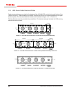
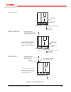
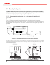
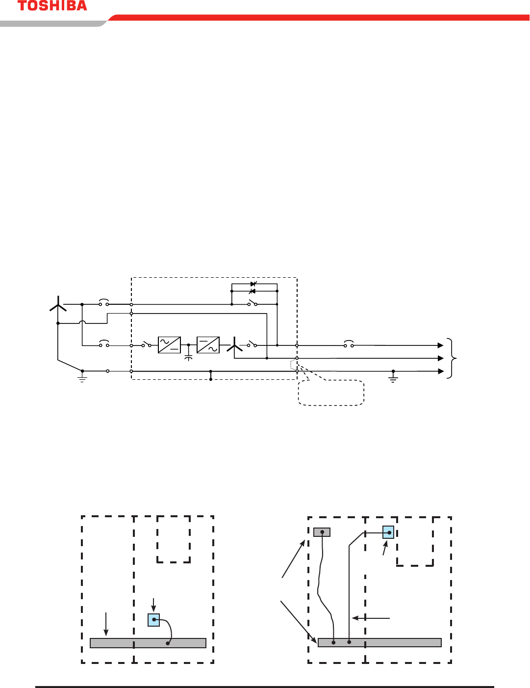
11.7.1 Recommended conguration (for 4 wire input with Input Neutral
grounded)
Figure 11.12 shows recommended grounding conguration when the input neutral is grounded.
The neutral line at the input source is usually grounded. The neutral terminal in the UPS cabinet should
be disconnected from the ground bus. The neutral connection for the UPS bypass input should be
grounded.
FIGURE 11.12 - GROUNDING CONFIGURATION WITH INPUT NEUTRAL GROUNDED
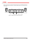
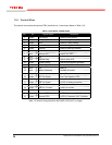
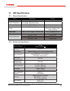
A 2 AWG (or 38 mm
2
) jumper cable is provided between the neutral terminal and ground bus in the UPS
cabinet. The qualied personnel should remove the jumper cable in this conguration. The jumper cable
location is illustrated below.
FIGURE 11.13 - JUMPER CABLE BETWEEN THE NEUTRAL TERMINAL & GROUND BUS
N
G
3
φ
3φ
3
φ
N
G
< UPS Cabinet >
N
3φ
3
φ
G
Input Source
Remove
Jumper Cable
G
N
3
φ
To the
Load
N
G
3
φ
3
φ
3
φ
N
G
< UPS Cabinet >
N
3
φ
3
φ
G
Input Source
Jumper Cable
Remains in Place
G
N
3
φ
To the
Load
N
G
3
φ
3
φ
3
φ
N
G
< UPS Cabinet >
3
φ
3
φ
G
Input Source
Jumper Cable
Remains in Place
G
N
3
φ
To the
Load
N
G
3
φ
3
φ
3
φ
N
G
< UPS Cabinet >
G
N
3
φ
3
φ
To the
Load
Out
p
ut Distribution
3
φ
3
φ
G
Input Source
B
φ
Remove
Jumper Cable
Ground
Bus
Remove
Jumper
Cable
Neutral
Terminal
Ground
Bus
Remove
Jumper
Cable
300 kVA
100-225 kVA
Neutral
Terminal