


TOSHIBA
3.0 Installation Precautions
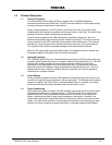
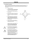
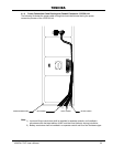
Based on the 4200FA UPS external dimensions and the way the outer panels are removed; minimum
amounts of unobstructed space around the unit are necessary for ventilation and maintenance
access. The following section and Fig. 3.1 shows the minimum clearances required for proper UPS
site installation.
3.1 Equipment Placement
1)
2)
3)
4)
5)
6)
7)
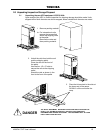
Do not install the UPS on an inclined surface,
or areas that are subject to frequent vibrations
or jolting. This could damage UPS circuits.
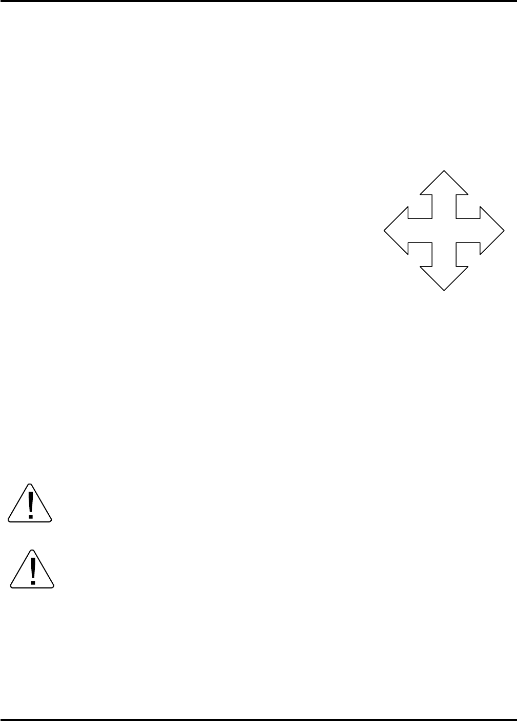
LEFT
6” (152mm)
RIGHT
6” (152mm)
REAR
6” (152mm)
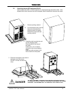
Do not allow liquids or foreign objects to get
inside the UPS.
Allow at least 20” (500 mm) on the front side
and 6" (152 mm) on the rear and sides of the
UPS unit for air ventilation and maintenance
access.
Do not install the UPS in a location that is
subject to high humidity. Also, do not install
the unit in areas that are exposed to direct
sunlight, or contaminated areas subject to
high levels of airborne dust, metal particles, or
flammable gasses.
FRONT
20” (500mm)
Fig 3.1
Verify the ventilation and air conditioning
system at the site is capable of removing the
heat generated by the UPS.
Ambient temperature range for operating the
UPS is 32 – 104 °F (0 – 40 °C); 77 °F
(25 °C) is the recommended operating
temperature for maximum battery life.
Avoid installation near sources of electrical
noise. Always make sure that the unit's
ground is intact to prevent electrical shock
and help prevent electrical noise.
This UPS generates and radiates radio-
frequency energy during operation. Although
RFI noise filters are installed inside the unit
there is no guarantee that the UPS will not
influence some sensitive devices, which are
operating in near proximity. If such
interference occurs, the UPS should either be
installed farther away from the affected
equipment and/or powered from a different
source than the affected equipment.
4200FA CT/XT User’s Manual 18