


TOSHIBA
4.5 Communication Interface
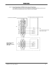
4.5.1 Remote Contact
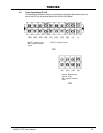
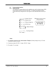
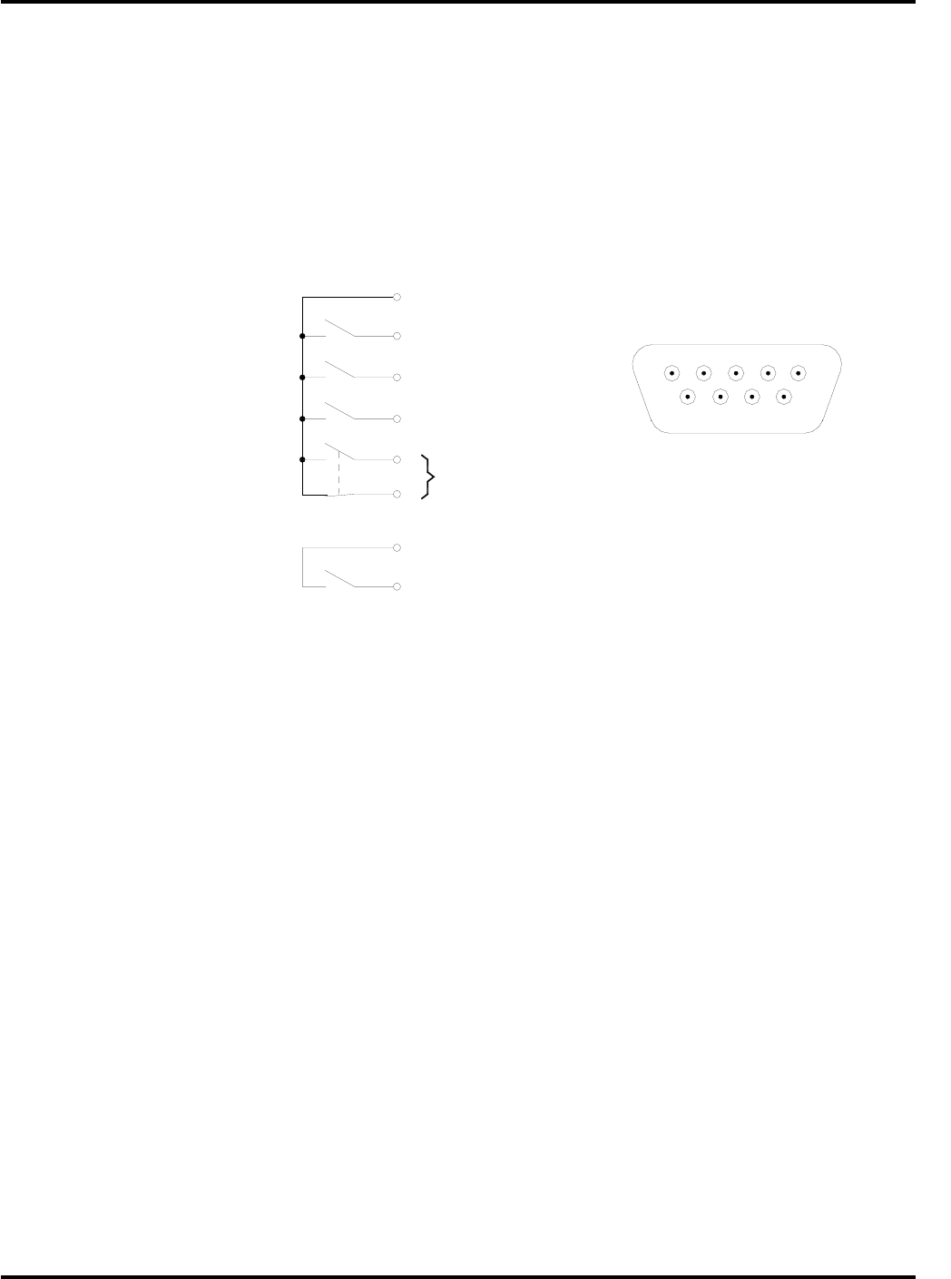
This interface is a standard feature and is available as dry switch contacts through a DB9
male connector located on the front of the UPS. The following schematic shows the
contact state and pin assignment for each signal and the associated DB9 connector pin-
out.
5 System Common
6 Bypass Active
Fault Signal Detect
1
2
8 UPS On-line
7 Battery Voltage Low
Battery Discharge
9
4
DB9 Male Connector Outline
(facing connector)
1 2 3 4 5
6 7 8 9
Notes:
1) Pin “switches” are shown in their inactive states. Example: (if battery voltage is low, pin 7 will be
connected to System Common).
2) Contacts are rated at 30 VDC, 0.1 amps; 125 VAC, 3 amps.
3) Pin number “3” is not used.
4200FA CT/XT User’s Manual 29