


October 2000 © TOSHIBA TEC 5 - 1 KK-1600 CIRCUIT DESCRIPTION
5. CIRCUIT DESCRIPTION
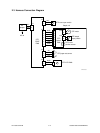
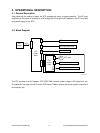
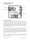
5.1 PWA Block Diagram
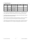
5.2 Functional Description
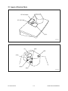
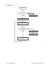
The STP operates the stapler through the STP controller PWA. When the power of the copier is turned
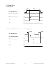
on, a power supply is also delivered to the STP to enable stapling. When paper is loaded into the stapler,
the STP paper set sensor detects the presence of paper (changing from “High” to “Low”), and 200 ms
later the CW signal turns ON (changing from “Low” to “High”) to operate the STP motor forward. When
the motor operates, the gears and cams of the stapler operate for stapling. When the STP home position
sensor detects the home position of the stapler (changing from “High” to “Low”) after the CW signal is
activated, the CW signal turns OFF.
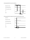
If the STP home position sensor remains at “High” level (a failure to return to the home position) for some
reason even if a fixed time (approx. 900 ms) has elapsed after the CW signal turns ON, the CW signal
turns OFF and 100 ms later the CCW signal is turned ON (changing from “Low” to “High”) to operate the
STP motor reversely. In practice, however, if the STP has locked up mechanically, an overload occurs so
that the fuse installed on the STP CONT PWA will blow or the protective circuit of the AC adapter will
function to cut the delivery of the power supply (shutdown).
If the stapler is not at the home position when the power is turned on (“High” level), about 60 ms later the
CCW signal is turned ON (changing from “Low” to “High”) to operate the motor reversely allowing the
stapler to return to the home position.
STP 05-01-01
24V
J2
J5J4J3
FU1
STP cover open
switch
STP AC adapter
STP LED PWA
STP sensor PWA
STP paper set
sensor
5V
5V
24V
5V
GND
GND
GND
1
2
1
2
1
2
3
1
5V
3
2
GND
1
GND
CW
PAPER_SENS
STPL_H/P
HOOK_SW
CCW
4
3
2
5
6
7
J1
Q3
switching
regulator
Motor
controll
circuit
Motor drive
circuit
Motor drive
circuit