


October 2000 © TOSHIBA TEC 1 KK-1600 CONTENTS
CONTENTS
1. SPECIFICATIONS....................................................................................................... 1-1
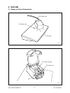
2. OUTLINE ..................................................................................................................... 2-1
2.1 Names of Various Components ........................................................................................ 2-1
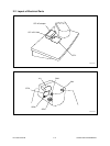
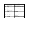
2.2 Layout of Electrical Parts ................................................................................................. 2-2
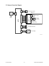
2.3 Harness Connection Diagram .......................................................................................... 2-4
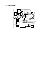
2.4 Board Assembly ............................................................................................................... 2-5
3. OPERATIONAL DESCRIPTION ................................................................................. 3-1
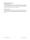
3.1 General Description ......................................................................................................... 3-1
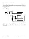
3.2 Block Diagram .................................................................................................................. 3-1
3.3 Detection of Abnormal Status .......................................................................................... 3-2
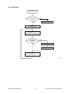
3.4 Flow Chart........................................................................................................................ 3-3
4. MECHANICAL DESCRIPTION ................................................................................... 4-1
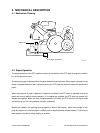
4.1 Mechanism Drawing ......................................................................................................... 4-1
4.2 Staple Operation .............................................................................................................. 4-1
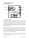
5. CIRCUIT DESCRIPTION ............................................................................................ 5-1
5.1 PWA Block Diagram ......................................................................................................... 5-1
5.2 Functional Description...................................................................................................... 5-1
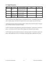
5.3 Signal Description ............................................................................................................ 5-2
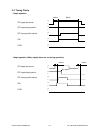
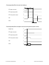
5.4 Timing Charts................................................................................................................... 5-3
6. DISASSEMBLY AND REPLACEMENT ...................................................................... 6-1