


Chapter 4 Replacement Procedures
Satellite L640/L645, Satellite Pro L640/Pro L645 Maintenance Manual (960-Q08)
4.21 Power Board………………………………………………………………………….68
4.22 SIM Board………………………...………………………………………………….70
Figures
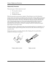
Figure 4-2-1 Remove the battery pack................................................................................. 8
Figure 4-2-2 Install the battery pack.................................................................................. 10
Figure 4-3-1 Turn the computer upside down ................................................................... 11
Figure 4-3-2 Remove HDD/SSD assembly ....................................................................... 12
Figure 4-3-3 Remove HDD/SSD....................................................................................... 13
Figure 4-4-1 Remove memory slot cover .......................................................................... 15
Figure 4-4-2 Remove a memory module........................................................................... 15
Figure 4-4-3 Insert a memory module ............................................................................... 16
Figure 4-5-1 Remove 2 screws for KB Holder.................................................................. 18
Figure 4-5-2 Remove 3 screws for Keyboard.................................................................... 18
Figure 4-6-1 Wireless LAN card ....................................................................................... 20
Figure 4-6-2 Remove a wireless LAN card ....................................................................... 21
Figure 4-7-1 3G module card............................................................................................. 23
Figure 4-7-2 Remove a 3G module card............................................................................ 24
Figure 4-7-3 Installing a 3G module card.......................................................................... 25
Figure 4-8-1 Remove the screw on ODD Bezel and ODD................................................ 26
Figure 4-8-2 Remove the screws(from bottom side) ......................................................... 27
Figure 4-8-3 Remove the screws(from top side) ............................................................... 27
Figure 4-8-4 Remove the Wireless Antenna...................................................................... 28
Figure 4-8-5 Remove the LCD cable from mother board.................................................. 29
Figure 4-8-6 Remove the LCD cable from LCD panel ..................................................... 29
Figure 4-8-7 Remove the hinge screws ............................................................................. 29
Figure 4-8-8 Securing the hinge screws............................................................................. 31
Figure 4-8-9 Connecting LCD harness to the mother board.............................................. 32
Figure 4-8-10 Arrange and connect Wireless LAN antenna ............................................... 32
Figure 4-9-1 Remove the screws (back) ............................................................................ 33