


Chapter 4 Replacement Procedures
================================================================================================================================================================================================
================================================================================================================================================================================================
================================================================================================================================================================================================
================================================================================================================================================================================================
================================================================================================================================================================================================
=============================================================2
4.1 Overview
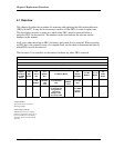
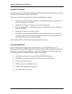
This chapter describes the procedure for removing and replacing the field replaceable units
(FRUs) in the PC. It may not be necessary to remove all the FRUs in order to replace one.
The chart below provides a guide as to which other FRUs must be removed before a
particular FRU can be removed. The numbers in the chart indicate the relevant section
numbers in this manual.
In all cases when removing an FRU, the battery pack must also be removed. When repairing
an FRU that is the potential cause of a computer fault, use the chart to determine the order in
which FRUs need to be removed.
The tilt stand, if it is installed, can be removed without any other FRUs removed.
4.2 Battery Pack
4.3 HDD/SSD
4.4 Memory Module
4.5 Key board
4.9 TOP Cover Assembly
4.18
Optical
Disc Drive
and ODD
Bezel
4.22
SIM
Board
4.10
Touch
pad
4.17
Speaker
Box
4.12 Mother Board
4.8
Display
Assembly
4.19 BT
Module
4.11 I/O
Board
4.21
Power
Board
4.20
Modem
4.6
Wireless
LAN
Card
4.13 CPU Heat
Sink
4.7 3G
Module
Card
4.14 LCD
Unit
4.16 Application
for Thermal pad
and grease on
CPU, North
Bridge, V-ram,
Chock and VGA
4.15 WEB
Camera
Module
Chart Notation
The chart shows the case for the
following example:
Removing a LCD unit
All FRUs down to the “4.2 Battery
p
ac
k
”to”4.5 Keyboard” and “4.9 Top
Cover Assembly” and “4.8 Display
Assembly” above LCD unit must be
removed.
Satellite L640/L645, Satellite Pro L640/Pro L645 Maintenance Manual (960-Q08)