


Chapter 4 Replacement Procedures
Satellite L640/L645, Satellite Pro L640/Pro L645 Maintenance Manual (960-Q08)
Figure 4-9-2 Remove the screws (front) and Top cover assembly.................................... 34
Figure 4-9-3 Disconnect the touch pad cable/BT cable/speaker cable/power cable ......... 34
Figure 4-10-1 Remove the touch pad FFC cable………..………….……………………...36
Figure 4-10-2 Loose the screws…………………...…………………………….................37
Figure 4-10-3 Remove the touchpad and touchpad board…………………………………37
Figure 4-11-1 Remove the I/O Board .................................................................................. 39
Figure 4-12-1 Remove the mother board............................................................................. 41
Figure 4-12-2 Remove RTC battery-step_1 ........................................................................ 43
Figure 4-12-3 Remove RTC battery-step_2 ........................................................................ 44
Figure 4-12-4 Install the RTC Battery................................................................................. 45
Figure 4-13-1 Remove the CPU heat sink ........................................................................... 46
Figure 4-14-1 Remove the display mask ............................................................................. 48
Figure 4-14-2 Remove the LCD unit................................................................................... 49
Figure 4-14-3 Remove the LCD hinge ................................................................................ 50
Figure 4-15-1 Remove the connector of Web Camera module………….………………...52
Figure 4-15-2 Peel off the glue of Web Camera module………….……………….............53
Figure 4-16-1 Intel &AMD Thermal pad and grease on CPU, NB, V-ram, chock and
VGA………………………………………………………………………...55
Figure 4-17-1 Removing the securing screws at left side………….………………………57
Figure 4-17-2 Removing the securing screws at right side………….……………………..58
Figure 4-17-3 Removing the Speaker Box………….……………………………………..58
Figure 4-18-1 Remove memory slot cover………….……………………………………..60
Figure 4-18-2 Remove the Screw on ODD Bezel and ODD….…………………………...60
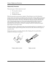
Figure 4-18-3 Remove the ODD………….……………………………………………….61
Figure 4-18-4 Remove the ODD Bezel………….………………………………………...61
Figure 4-18-5 Installing the ODD Bezel………….……………………………………….62
Figure 4-18-6 Installing the ODD………….………………………………………………62
Figure 4-18-7 Securing screw on ODD Bezel………….…………………………………..63
Figure 4-18-8 Securing the screws on RAM Door….……………………………………...63
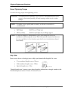
Figure 4-19-1 Remove the Bluetooth cable….……………………………………..............64
Figure 4-19-2 Remove the Bluetooth module….. ….……………………………………...64
Figure 4-20-1 Remove the modem…………………..….………………………………….66