


4 Replacement Procedures 4.7 Logic Upper Assembly
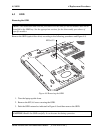
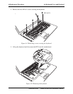
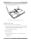
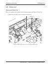
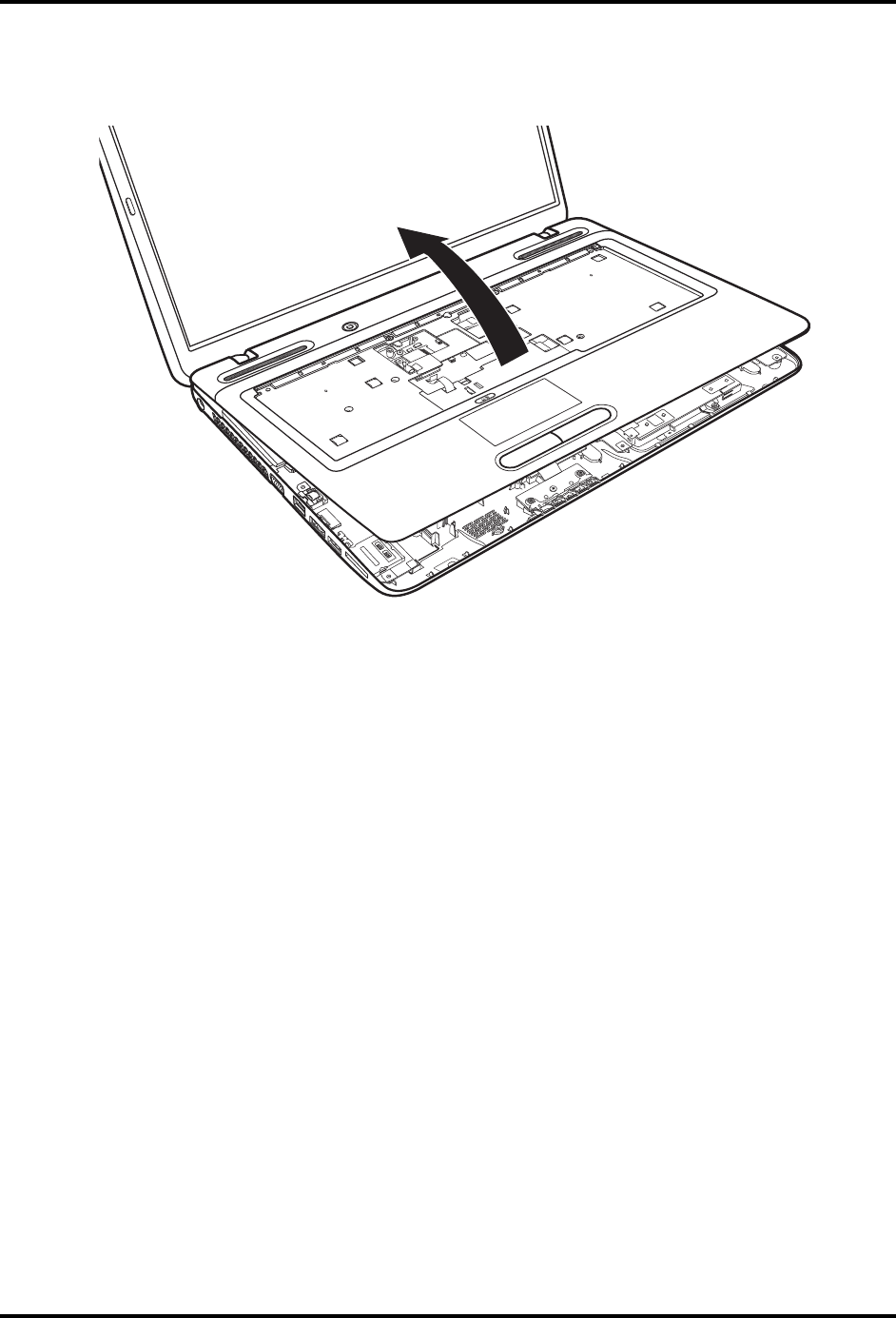
5. Grab the edge of the opening in the middle of the logic upper assembly and pull up to
remove it from the laptop as shown in Figure 4.15.
Figure 4.15 Removing the logic upper assembly from the laptop
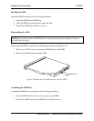
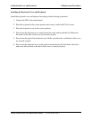
Installing the Logic Upper Assembly
Install the logic upper assembly according to the following procedures.
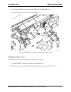
1. Seat the logic upper assembly to the front of the laptop, and adjust to the correct position.
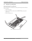
2. Press down the logic upper assembly, starting from the top and toward the bottom. Make
sure that the hooks on the back of the assembly are securely in place.
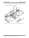
3. Connect the touchpad FFC to the motherboard.
4. Secure five M2.5x5 screws.
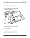
5. Turn the laptop upside down.
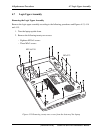
6. Secure the logic upper assembly with twenty-one screws as indicated in Figure 4.13:
− Eighteen M2.5x5 screws
− Three M2x2 screws
[CONFIDENTIAL] Satellite L670/Pro L670 Maintenance Manual