


4 Replacement Procedures 4.1 General
4-2
[CONFIDENTIAL]
Satellite P200
/ P205
Series Maintenance Manual
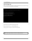
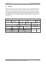
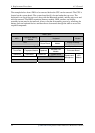
The example below shows FRUs to be removed before the CPU can be removed. The CPU is
located on the system board. The system board itself is located under the top cover. The
keyboard is on top of the top cover, along with the Bluetooth module, and the strip cover and
must be removed. The HDD, expansion memory module, ODD, modem, and display
assembly in turn need to be removed. Always start the disassembly process by removing the
battery pack and optional devices and then move downwards through the table to access the
required component.
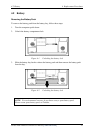
Battery pack
HDD
Expansion Memory
Module
Keyboard Modem
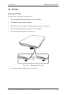
ODD
Function
Button Board
Bluetooth
Module
Display Assembly
Top Cover Display Mask
Touch Pad Fingerprint Module Speakers
Wireless LAN
Module
FL Inverter Board
Subwoofer USB Board System Fan System Board
VGA Board Heat Sink
Fan CPU
Camera and
Microphone
LCD
Module