


10
In addition to the above signals, the metallic housing of the DB9 connector is
connected to the shield section of the interface board. The shield section is attached
to the metal ground terminal on the bottom of the unit, where a ground wire can be
attached to connect the Profibus network cable shield to ground. Refer to section 4
of this document for more information related to grounding.
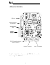
Drive Network Connectors
TTL-level. Uses standard RJ-45 style 8-pin modular connectors. Any standard
category-5 Ethernet cable (found in most electronics stores) 5 meters or less in
length can be used to connect the PBDP-110 to the drives.
MMI Port Connector
RS232-level. Use the DB9-to-RJ-45 cable supplied with the PBDP-110 kit to
interface with the unit via the Flashloader programming utility (refer to section 12).
Input/Output Data
The PBDP-110 presents a module interface, supporting 2 different modules
depending on the number of drives connected to the unit.
If the PBDP-110 is configured for 1 drive (the Channel A drive), the interface’s cyclic
data sizes are fixed at 16 bytes of output (control) data configured as four 32-bit
words, and 24 bytes of input (status) data configured as six 32-bit words.
If the PBDP-110 is configured for both drives (Channel A and B), the interface’s
cyclic data sizes are fixed at 32 bytes of output (control) data configured as eight 32-
bit words, and 48 bytes of input (status) data configured as twelve 32-bit words.
Via these data structures, any data item (commands, monitor data and parameters)
available in the drive can be accessed. For detailed explanations of the format and
usage of this data, refer to sections 9 and 10 of this document.
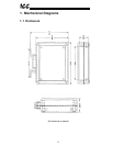
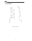
Versatile 3-Way DIN-Rail Mounting System
The interface unit enclosure is provided with a mounting clip attached to the rear of
the unit. This clip allows the unit to be mounted 3 different ways:
• For DIN rail mounting, snap the mounting clip onto a standard DIN rail, and
then snap the unit enclosure onto the clip’s retaining tabs. This allows easy
removal or repositioning of the unit on the DIN rail during wiring.
• For panel mounting, the mounting clip can be bolted directly to a flat panel via
the two bolt holes at the top and bottom of the clip. Refer to section 1.2 for
mounting clip mechanical details. Once the mounting clip is securely
attached to the panel, the unit enclosure can be snapped onto the clip’s
retaining tabs.
• For fixed DIN rail mounting, a combination of the above two techniques can
be employed. First, snap the mounting clip onto a DIN rail and position it in its
desired location. Then, the mounting clip can be bolted to the DIN rail support