


14
power to the drive has been removed. A hazard exists temporarily for
electrical shock even if the source power has been removed. Verify that the
CHARGE LED has gone out before continuing the installation process.
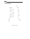
3. Attach the mounting clip and unit enclosure in your desired manner (refer to page
10 for more information).
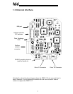
4. Remove the drive’s common serial communication port cover (refer to the
appropriate drive manual for instructions how to do this). Do not discard this
cover, as it should be reinstalled to minimize contamination of the port’s electrical
contacts if the interface is ever disconnected from the drive.
5. Connect the drive’s common serial communication port to “Channel A” of the
PBDP-110 with the communication cable (communication cable is not included
with the interface kit). When choosing cables for this connection, standard 24
AWG category 5 (CAT5) unshielded twisted-pair (UTP) 8-conductor cables found
in Ethernet networks in most office environments can be used. The maximum
allowable length for these cables is 5 meters. Although there are many varieties
and styles of CAT5 UTP cables available, ICC strongly recommends using only
high-quality cables from reputable manufacturers to guarantee optimal noise
immunity and cable longevity. Ensure that each end of the cable is fully seated
into the modular connector, and route the cable such that it is located well away
from any drive input power or motor wiring. Also take care to route the cable
away from any sharp edges or positions where it may be pinched.
6. Repeat steps 1, 2, 4 and 5 to connect another drive to “Channel B” on the
interface, if desired.
7. Connect the Profibus network cable to the DB9 connector marked “Network” on
the PBDP-110. If a ground cable is going to be used, attach the ground cable to
the terminal marked “Shield GND” on the bottom side of the PBDP-110 enclosure
(refer to section 4). Refer to the Profibus Specification for detailed network wiring
guidelines. Ensure that the Profibus network cable is tightly screwed onto the
DB9 connector, and route the cable such that it is located well away from any
drive input power or motor wiring. Also take care to route the cable away from
any sharp edges or positions where it may be pinched.
8. Take a moment to verify that the PBDP-110 and all network cables have
sufficient clearance from drives, motors, or power-carrying electrical wiring.
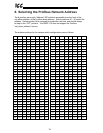
9. Configure the Profibus slave address via the DIP switches on the front of the
interface (refer to section 8).
10. Turn the power sources to all connected drives ON, and verify that the drives
function properly. If the drives do not appear to power up, or do not function
properly, immediately turn power OFF. Repeat steps 1 and 2 to remove all
power from the drives. Then, verify all connections. Contact ICC or your local
drive distributor or manufacturer for assistance if the problem persists.