


20
9. Exchanged Data Structures
9.1 Output (Control) Data Format
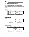
The size of the output data structure from the network master to the PBDP-110
depends on the module selected from the GSD file for the network configuration tool.
Module #1, intended for applications where only 1 drive is connected to the PBDP-
110 (via Channel A), is comprised of 16 bytes structured as four 32-bit words.
Module #2, intended for applications where drives are connected to both Channel A
and Channel B, is comprised of 32 bytes structured as eight 32-bit words.
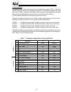
Offset Data Offset Data
0 Reserved 16 Reserved
1 Reserved 17 Reserved
2 Drive A command high byte 18 Drive B command high byte
3 Drive A command low byte 19 Drive B command low byte
4 Reserved 20 Reserved
5 Reserved 21 Reserved
6
Drive A frequency command
high byte
22
Drive B frequency command
high byte
7
Drive A frequency command
low byte
23
Drive B frequency command
low byte
8
Reserved /
Drive A action bits
24
Reserved /
Drive B action bits
9 Reserved 25 Reserved
10
Drive A parameter number
high byte
26
Drive B parameter number
high byte
11
Drive A parameter number
low byte
27
Drive B parameter number
low byte
12 Reserved 28 Reserved
13 Reserved 29 Reserved
14
Drive A parameter data to
write high byte
30
Drive B parameter data to
write high byte
15
Drive A parameter data to
write low byte
31
Drive B parameter data to
write low byte
Locations marked “Reserved” in the above table are reserved for future use.
Although any data placed in these locations is currently ignored, future firmware
releases may use these locations for data transfer.
The format of all information transferred for Drive B is identical to that for Drive A.
Therefore, all data descriptions given here apply equally for both Drives A and B.