


4.1 General 4 Replacement Procedures
4 1
4.1 General
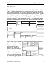
This chapter explains how to disassemble the computer and replace Field Replaceable Units
(FRUs). Some replacement procedures may not require you to remove all the surrounding
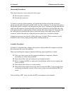
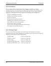
FRUs to replace only one FRU. The chart below shows the FRUs in the order in which they
should be removed in a top-down manner, irrespective of their physical locations. The FRUs
shown in the top area of the chart should normally be removed before removing the FRUs
shown in the bottom area. To replace the FRUs, first identify the suspect FRU for the system
failure. Next, according to this chart, determine the FRUs that need to be removed before
removing the suspect FRU. After you determine those FRUs, go to the appropriate sections
according to the section numbers shown in the boxes. Then start removal and replacement.
4.9
Top Cover
4. 2
HDD
4. 3
ODD Bay Module
4. 20
Touch Pad and
Touch Pad Board
4. 7
Wireless LAN Card
4. 4
Speaker
cover
and
Keyboard
4. 5
4. 8
Display Assembly
4. 13
VGA Card
4. 12
System Board, AC-IN cable and Fan
4. 16
Display Mask
4. 17
FL Inverter Board
4. 19
LCD Modules
4. 14
Cooling Module
4. 15
CPU
Switch Board
4.11
USBandCRTCable,
Fingerprint Board
and
Bluetooth Card
4. 10
Speakers
4. 6
MDC Module
4. 18
CCD Board and MIC
SystemBoard
LCDModule
4.9
Top Cover
4.2
HDD
4.3
ODDBay Module
4.20
Touch Pad and
TouchPadBoard
4.7
WirelessLANCard
4.4
Speaker
cover
and
Keyboard
4.5
4.8
DisplayAssembly
4.13
VGACard
4.12
SystemBoard, AC-INcable andFan
4.16
DisplayMask
4.17
FLInverterBoard
4.19
LCDModules
4.14
CoolingModule
4.15
CPU
SwitchBoard
4.11
USBand CRT Cable,
FingerprintBoard
and
BluetoothCard
4.10
Speakers
4.6
MDCModule
4.18
CCDBoard andMIC
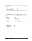
How to use the chart (two examples):
• For removing the System Board:
First, remove the top cover with the
display assembly. Then, remove the
HDD, selectable bay module,
Bluetooth card, keyboard, and
wireless LAN card, all of which are
shown above the top cover with the
display assembly.
• For removing the LCD Module:
First, remove the display mask and
FL inverter board, both of which are
shown above the LCD module.
Qosmio F40/F45 Maintenance Manual 4-1