


TMP92CZ26A
92CZ26A-300
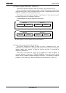
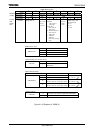
(4) Capture registers (TB0CP0H/L, TB0CP1H/L)
These 16-bit registers are used to latch the values in the up counter (UC10).
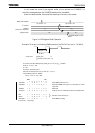
Data in the capture registers should be read all 16 bits. For example, using a 2-byte
data load instruction or two 1-byte data load instructions. The least significant byte is
read first, followed by the most significant byte.
(during capture is read, capture operation is prohibited. In that case, the lower 8
bits should be read first, followed by the 8 bits.)
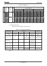
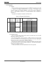
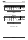
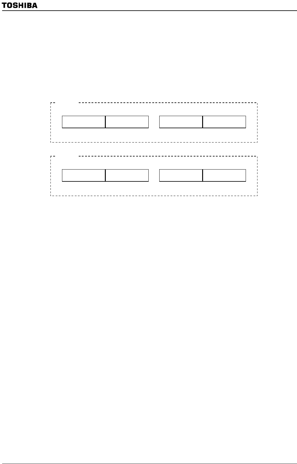
The addresses of the capture registers are as follows;
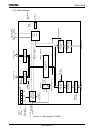
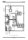
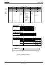
(5) Capture input and external interrupt control
This circuit controls the timing to latch the value of up-counter UC10 into
TB0CP0H/L and TB0CP1H/L, and generates external interrupt.The latch timing of
capture register and selection of edge for external interrupt is controlled by
TB0MOD<TB0CPM1:0>.
The value in the up-counter (UC10) can be loaded into a capture register by
software. Whenever 0 is written to TB0MOD<TB0CP0I>, the current value in the up
counter (UC10) is loaded into capture register TB0CP0H/L. It is necessary to keep the
prescaler in RUN mode (e.g., TB0RUN<TB0PRUN> must be held at a value of 1).
Upper 8 bits
(TB0CP0H)
Lower 8 bits
(TB0CP0L)
TB0CP0H/L
118DH 118CH
Upper 8 bits
(TB0CP1H)
Lower 8 bits
(TB0CP1L)
TB0CP1H/L
118FH 118EH
TMRB0
Upper 8 bits
(TB1CP0H)
Lower 8 bits
(TB1CP0L)
TB1CP0H/L
119DH 119CH
Upper 8 bits
(TB1CP1H)
Lower 8 bits
(TB1CP1L)
TB1CP1H/L
119FH 119EH
TMRB1
The capture registers are read-only registers and thus cannot be written to.