


E6581371c
- 9 -
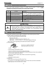
3.2. VF-FS1 communication parameters
Set up the inverter parameters as follows. To update, reset the power of inverter. If these
parameters are not set to correct value, this unit can not work normally.
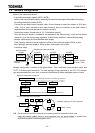
Title Function Description
cmod Command mode selection
fmod Setpoint mode selection
While L
ONWORKS communication option is installed
into VF-FS1, The network command and setpoint are
prior to cmod/fmod. VF-FS1 front panel operation
is prior when LOC lamp on the front panel turns on.
f800 Communication speed Set “1: 19200bps” (default).
f801 Parity Set “1: Even” (default).
f803 Communication error trip time Set communication time out period.
f829 Communication protocol Set “1: MODBUS-RTU”
f851 Operation at network error
Set the behavior when “Receive heart beat timer”
overflow occurred.
Warning
Mandatory
Set up “Communication error trip function (f803, see the inverter instruction
manual for details)” to stop the inverter when this option unit is deactivated by an
unusual event such as tripping, an operating error, power outage, failure, etc.
Deactivated option unit may cause an accident, if the “Communication error trip
function” is not properly set up.
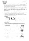
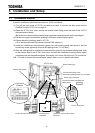
3.3. Network cable connection
Connect the LONWORKS
network cable to LONWORKS communication option as follows.
(1) Cable selection (a twisted pair cable with shield)
Use Level 4/22 AWG cable for the network cable.
- Recommended cable
Manufacturer: Showa Electric Wire & Cable Co., Ltd.
Model name: LW221S, 22AWG, 1P, With shield, Standard 300m/reel
Use 0.75mm
2
wire for grounding to the earth terminal (G/E) of the board.
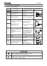
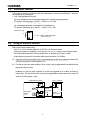
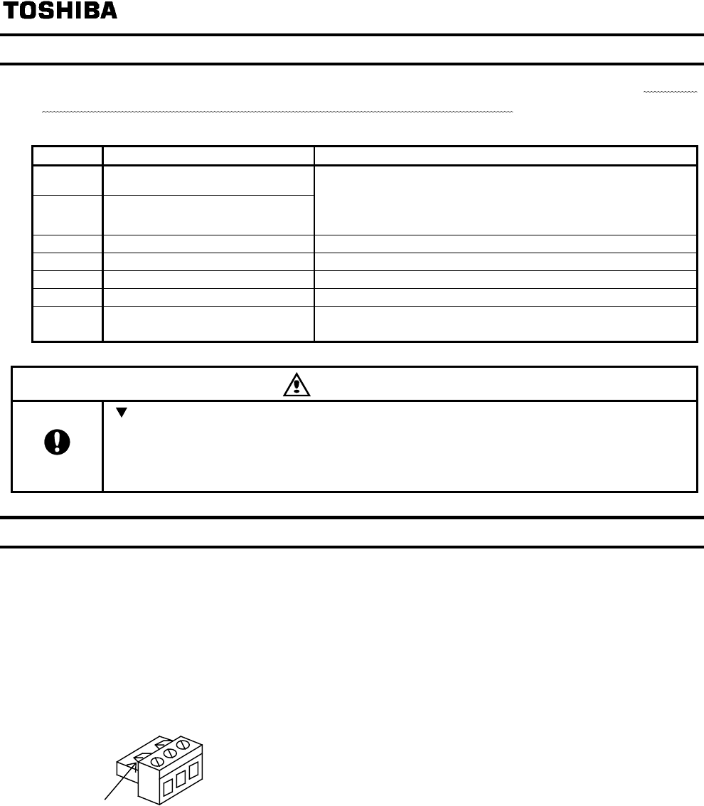
(2) Terminal blocks
NET
A
SHLD
NETB
Catches
Manufacturer: PHOENIX CONTACT
Model name: MSTB 2,5/3-ST-5.08
- Communication terminal NETA, NETB
Connect L
ONWORKS
transmission/reception data cable.
Polarity of the communication terminals NETA and NETB does not have to be considered.
- Communication shield terminal SHLD
Connect the shield of network cable. Refer to next section for grounding.
- G/E terminal
Connect the network ground.
(3) Connection
Cable sheath should be peeled off by about 7mm.
For wiring work, use a flat blade screwdriver with a 0.6mm thick and 3.5mm width blade.
Tightening torque for the terminal block is 0.5Nm.