


E6581371c
- 11 -
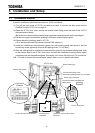
3.5. Termination resistor
Terminate the network bus with about 52.3ohm impedance to minimize the reflections. There are
two choices for the termination.
1. Free Topology Network Segment
Only one termination and may be placed anywhere on the free topology segment.
RC network (Following figure), with R1 = 52.3ohm +/-1%, 1/8W
2. Doubly Terminated Bus Topology Segment.
It is necessary to terminate at both ends of a twisted pair bus.
RC network (Following figure), with R1 = 105ohm +/-1%, 1/8W
C1 and C2 are required for connection to link power network.
C1, C2: Aluminum-electrolytic type
100uF, 50V min
+
C1
R1
+
C2
Terminal circuit
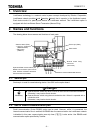
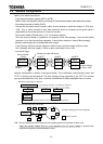
3.6. Wiring of a control terminal
Observe the following when wiring.
- Use 0.3 to 1.5mm
2
solid/stranded wire (AWG 22 to 16) for control cables.
- Remove the sheath of a cable about 7mm (6mm for FLA, FLB, FLC and G/E) from the end of cable.
- Use a flat-headed screwdriver with its blade 0.6mm in thickness and 3.5mm in width.
- Screw tightening torque for the terminal block screws should be 0.5 to 0.6Nm.
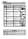
N.B.: Keep the control signal cables 20cm or more separate from the power cables to prevent from
malfunctioning due to electromagnetic noise.
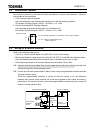
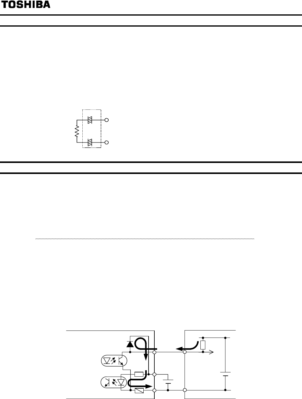
N.B.: Provide an inter-lock system stated in below, when using a programmable controller that has
the open collector output.
When the programmable controller is turned off with the inverter is on, the difference
between each control power potential will cause wrong signals to the inverter as shown in
below figure. Provide an inter-lock so that the programmable controller cannot be turned off
when the inverter power is alive.
COM
+24V
Inverte
r
internal +24V
External
+24V supply
VF-FS1 + LIU007ZProgrammable controller
Input terminal
Fuse blowout
detection
circuit
Fuse