


E6581371c
- 7 -
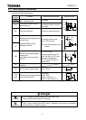
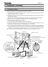
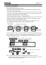
2.3. Description of terminals
<Control terminals specification>
Terminal
symbol
Function Electrical specifications Internal circuits
NETA
NETB
L
ONWORKS
transmission
data / reception data
no polarity
SHLD
L
ONWORKS
communication
shield terminal.
This terminal is not
connected to other circuits in
this board.
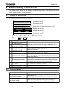
G/E Grounding terminal Connect to network ground
NETA
NETB
SHLD
FT-X1
Spark
gap
G/E
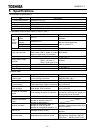
F
R
Multifunctional programmable
contact input.
SINK/SOURCE can be
selected with SW1.
No voltage contact input
24V
DC
, 5mA or less
N.B. Use contact parts for low
current.
F, R
CC
P24
4.7k
P24
PTC
SOURCESINK
820
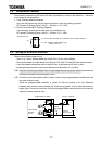
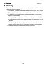
VIB
Multifunction programmable
analog input.
with internal pull-up resistor
for PTC
0 to 10V
DC
input
Using this terminal as PTC
input, set SW1 to PTC side
and set the parameters
(f645 and f646) to
proper value.
VIB
15k
VIB
P10
PTC
15k
3.3k
CC
Control circuit’s equipotential
terminal
P24 24 V
DC
power supply output 24V
DC
-50mA
P24
P24
PTC
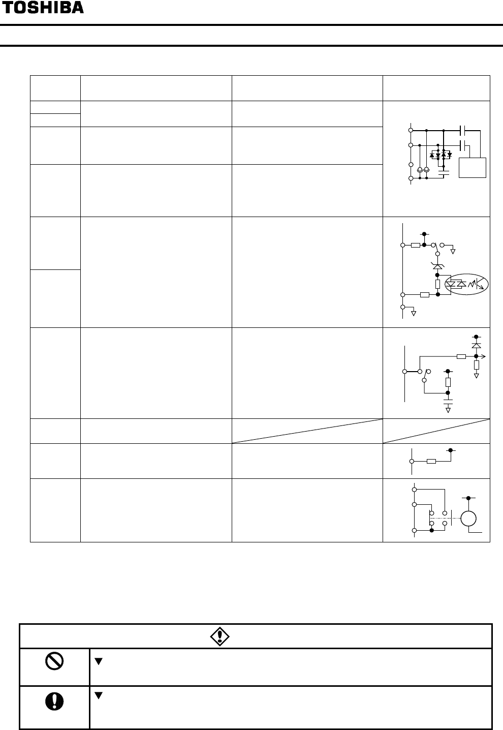
FLA
FLB
FLC
Multifunctional programmable
relay contact outputs
1c contact
30V
DC
-0.5A
250V
AC
-1A (cosφ =1
250V
AC
-0.5A (cosφ =0.4)
FLA
FLB
FLC
Ry
Danger
Prohibited
Do not change switches settings while the power is on.
It may lead to electric shocks or damage.
Mandatory
Turn off the motor operation signals before setting the parameter and the switch
(SW1), when changing the VIB function. Otherwise, the motor may suddenly
start and that may result in injuries.