


18/27 XM-7002B Rev.1.0
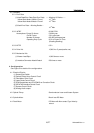
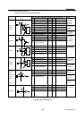
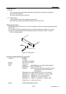
6.3. Connector
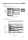
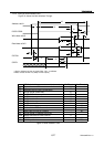
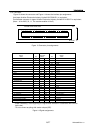
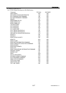
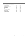
Figure 13 shows the connector and Figure 14 shows the interface pin assignments
Use Japan Aviation Electronics Industry Limited KX15-50KLD L or equivalent.
Conformable connector is Japan Aviation Electronics Industry Limited KX14-50K*D or equivalent.
(Note: * is No.2.85,5, 8, 11. The recommendation is No.5)
CD-ROM DRIVE REAR VIEW
TOP
BOTTOM
1
3
5
7
9
11
13
15
17
19
21
23
25
27
29
31
33
35
37
39
41
43
45
47
49
2
4
6
8
10
12
14
16
18
20
22
24
26
28
30
32
34
36
38
40
42
44
46
48
50
Figure 13 Connector pin assignments
Connector
contact
1
3
5
7
9
11
13
15
17
19
21
23
25
27
29
31
33
35
37
39
41
43
2
4
6
8
10
12
14
16
18
20
22
24
26
28
30
32
34
36
38
40
42
44
49
48
50
47
Vender unique *
Signal
name
Digital Ground
DD8
DD9
DD10
DD11
DD12
DD13
DD14
DD15
DMARQ
/DIOR: /HDMARDY: HSTROBE
/DMACK
/IOCS16
/PDIAG
DA2
/CS3FX
Ground
Ground
Audio R-CH
Ground
+5 V(LOGIC)
+5 V(MOTOR)
Signal
name
N.C (OPEN)
Device Config.(CSEL)
/RESET
DD7
DD6
DD5
DD4
DD3
DD2
DD1
DD0
Ground
Ground
/DIOW: STOP
IORDY: /DDMARDY: DSTROBE
INTRQ
DA1
DA0
/CS1FX
/DASP
+5 V(LOGIC)
Audio L-CH
+5 V(MOTOR)
Audio Ground
45
46
I/O
I/O
I/O
I/O
I/O
I/O
I/O
I/O
I/O
I/O
I
I
O
I
I
O
I
O
I
I
I
I/O
I
I
I
I/O
I/O
I/O
I/O
I/O
I/O
I/O
I/O
I/O
I
O
I
I
O
O
I
I
+5 V(MOTOR)
Digital Ground
Digital Ground
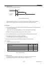
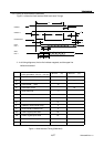
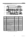
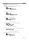
A slash character(/) at the beginning of a signal name indicates it is asserted at the low level
(active low).
* Do not connect anything with vender unique (50P).
Figure 14 Signal assignments