


TL-SF2226P+/TL-SL2226P+ Remote Smart Switch User Guide
Chapter 4: Explanation of Switch Appearance and the
Method of Connecting Switch
This chapter covers more details about front panel, rear panel, LED and extension
module of the switch.
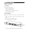
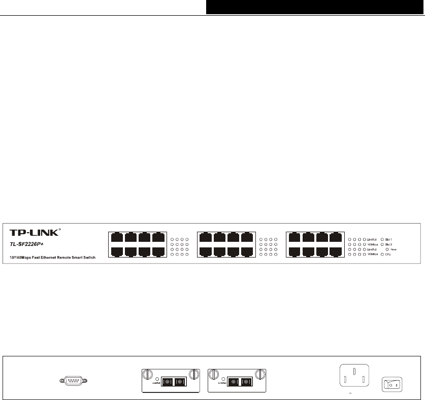
4.1 Front Panel
There are 24 10/100Mbps ports and LED indicators on the front panel of the
TL-SF2226P+.
17 19 21 23
18 20 22 24
9111315
10 12 14 16
1357
2468
Figure 4-1 Front Panel of the TL-SF2226P+
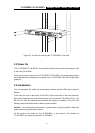
4.2 Rear Panel
Console
Slot 2Slot 1
110-260V 50-60Hz 0.6A
TX RX TX RX
Figure 4-2 Rear Panel of the TL-SF2226P+
There is a power switch, a power connector, a console (RS232) port and 2 extension
module slots on the rear panel.
Power Connector
The AC power connector is a standard three-pronged connector that supports the power
cord. Plug the female connector of the provided power cord into the socket, and the male
side of the cord into a power outlet. Supported input voltage range is from 100 to 240
VAC at 50-60Hz.
Console Port
The console port or RS232 port on the right of the rear panel is the connection port with
PC when Out-of-Band management. (For more details, please refer to Chapter 6).
Module Slot
The module slots can be inserted with 10/100M module card (TL-SF2226P+) or
10/100/1000M or a 1000M Base-X module card (TL-SL2226P+).
- 6 -