


15
CPSMC08xx-100 PointSystem
™
Chassis
power supply
3.2.2 DC Auxiliary Power Supply
• This product is intended to be used in a restricted access location. Proper earthing
(grounding) is required to ensure safe operation. Grounding terminals are provided
(section 4.1.3) for proper grounding of the device as per customer installation
requirements and local electrical codes. Prior to installation, use a
voltmeter/ohmmeter to check the wiring for the presence of earth ground.
• A readily accessible disconnect device as part of the building installation shall be
incorporated into the fixed wiring. The disconnect device (a 48 VDC, 15 or 20A
circuit breaker or switch) must be included in the ungrounded supply conductor.
Overcurrent protection must be a 48 VDC, 15 or 20A fuse or circuit breaker.
Read and follow all warning notices & instructions marked on the product or
included in the manual.
CAUTION: All installation and service must be performed by qualified service
personnel.
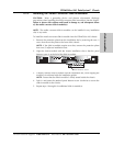
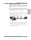
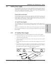
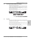
To power the CPSMC08xx-100 chassis through the DC auxiliary power supply:
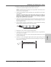
1. Connect the female end of the external power converter to the auxiliary power
inlet on the back of the chassis.
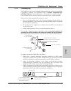
2. Connect the +48-VDC terminal to the connector marked “+”. Turn the terminal
screw clockwise to secure.
3. Connect the -48-VDC terminal to the connector marked “-”. Turn the terminal
screw clockwise to secure.
4. Connect the ground terminal to the connector marked “chassis ground”. Turn
the terminal screw clockwise to secure.
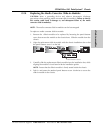
5. Verify that Auxiliary power supply is connected properly by disconnecting the
primary power supply, and then by observing the illuminated power LEDs on
the installed slide-in-modules and by the chassis’ fan operation.
24 hour Technical Support: 1-800-260-1312 -- International: 00-1-952-941-7600
Mpls, MN 55344
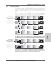
Input Power:
110-240 VAC
1.6A max. (60W max)
50/60 Hz
Auxiliary Power Inlet
External Power
Converter
+
GND
–