


16
24-Hour Technical Support: 1-800-260-1312 International: 00-1-952-941-7600
Operation -- continued
Copper/fiber status LEDs -- continued
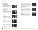
Copper LEDs
The function of the copper port LEDs (1, 2, 3, and 4) are as follows:
100MB ON The copper port has established a link at 100 MB/s.
100MB Flashing The copper port is transmitting signals at 100 Mb/s.
10MB ON The copper port has established a link at 10 MB/s.
10MB Flashing The copper port is transmitting signals at 10 Mb/s.
FD ON The copper port is in full-duplex mode.
FD OFF The copper port is in half-duplex mode.
Fiber LEDs
The functions of the fiber port LEDs (2 and 5) are as follows:
100MB ON The fiber port has established a link.
100MB Flashing The fiber port is transmitting signals.
10MB -- N/A
10MB -- N/A.
FD ON The fiber port is in full-duplex mode.
FD OFF The fiber port is in half-duplex mode.
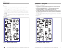
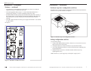
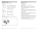
Fault (red) LED
Fault LED ON (red) indicates that the microcontroller did not initialize correctly; as a
result, the switch will not power up.
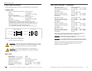
Fiber Port
Copper Port
Fault LED
Figure 13: Fault LED
SIBTF10xx-1xx-Mx
techsupport@transition.com -- Click the “Transition Now” link for a live Web chat.
17
Operation -- continued
Product Features
Immunity standards
The industrial switch is designed to meet EN61000-6-2, IEEE1613.
Congestion reduction
The SIBTF10xx-1xx industrial switch does not forward collision signals or error
packets from one collision domain to another, which improves baseline-network
performance. In addition, the industrial switch filters packets destined for local
devices, which reduces network congestion.
Rate conversion
The SIBTF10xx-1xx industrial switch allows connecting 10Mb/s terminal devices on a
10Base-T legacy Ethernet copper network and/or 100Mb/s terminal devices on a
100Base-TX fast Ethernet copper network to 100Mb/s terminal devices on a 100Base
FX fast Ethernet fiber network.
Full-Duplex network
In a full-duplex network, maximum cable lengths are determined by the type of cables
used. See cable specifications section for the different SIBTF10xx-1xx models. The
512-Bit Rule does not apply in a full-duplex network.
Half-Duplex network (512-Bit Rule)
In a half-duplex network, the maximum cable lengths are determined by the round trip
delay limitations of each fast Ethernet collision domain. (A collision domain is the
longest path between any two terminal devices: e.g., a terminal, switch, or router.)
The 512-Bit Rule determines the maximum length of cable permitted by calculating
the round-trip delay in bit-times (BT) of a particular collision domain. If the result is
less than or equal to 512 BT, the path is good.
For more information on the 512-Bit Rule, see the white paper titled “Collision
Domains” on the Transition Networks website at: www.transition.com.