20
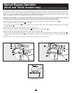
Manual Bypass Operation
(6kVA and 10kVA models only) (for power module maintenance or replacement)
The following procedure only applies to UPS system configurations that include a 6kVA or 10kVA transformer module. The procedure
details how to service or replace the power module while supplying equipment connected to the transformer module with utility power.
NOTE: since the power module and battery module will be disconnected during the procedure, they will be unable to supply battery backup
support to equipment connected to the transformer module in the event of a blackout.
WARNING! For qualified service personnel only. Failure to follow this procedure completely will not adequately power down the
UPS power module, resulting in the continued risk of death or injury from potential contact with high voltage.
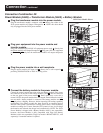
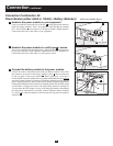
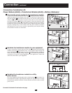
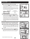
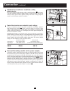
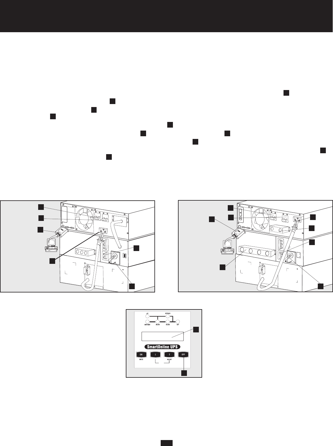
1. Disable PowerAlert Software and disconnect communication cable from the power module’s communication ports
A
.
2. Turn transformer module’s Bypass Switch
B
to “BYPASS”.
3. Press power module’s OFF Button
C
, if power module is powered, until a beep is heard and a “BYPASS MODE” message is displayed
in the LCD panel
D
.
4. Turn off the transformer module's double-pole AC to UPS breaker
E
.
5. Turn off the power module’s double-pole input breaker
F
and double-pole output breaker
G
.
6. Disconnect battery module cable from the power module’s battery connector
H
.
7. FOR 10kVA POWER MODULES ONLY: Use a voltage meter to check the cable connecting the power module’s terminal blocks
I
to
the transformer module’s terminal blocks
J
to ensure the power module is no longer powered. Once it is no longer powered, remove the
cabling.
The power module is now safely powered down and maintenance/replacement can be performed.
NORMAL
BY
PAS
S
N
O
R
M
A
L
B
Y
PA
S
S
6kVA Models (Rear Panel)
10kVA Models (Rear Panel)
A
B
F
G
A
B
F
G
I
E
D
C
6kVA & 10kVA Models
(Front Panel)
H
E
H
J


