


123413 12
7
10 11985
6
3
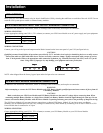
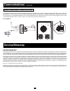
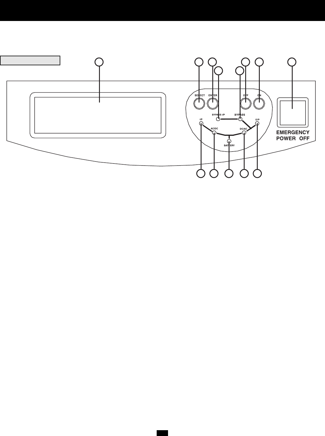
Control Panel
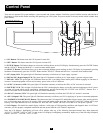
There are two separate UPS system modules: a power module and a battery module. Familiarize yourself with the location and function of
the features on each module before installing and operating your UPS system. The power module is the only module which includes front
panel features.
FRONT PANEL
1. “ON” Button: This button turns the UPS System's inverter ON.
2. “OFF” Button: This button turns the UPS System's inverter OFF.
3. “ENTER” Button: This button changes or selects the variables shown on the LCD Display. Simultaneously press the “ENTER” Button
and the “SELECT” Button and hold for a ¼ second to mute audible alarm.
4. “SELECT” Button: This button allows you to browse through different power readings on the LCD Display by momentarily pressing
the button. Simultaneously press the “ENTER” Button and the “SELECT” Button and hold for a ¼ second to mute audible alarm.
5. “I/P” (Input) LED: This green light will illuminate constantly to indicate an AC input supply is present.
6. “BYPASS I/P” (Bypass Input) LED: This green light will illuminate to indicate an AC input supply is present at bypass input.
7. “BYPASS” LED: This green light will illuminate when the UPS is providing filtered mains power without engaging its converter or
inverter. Connected equipment will not receive battery power in the event of a blackout.
8. “AC/DC” (Converter) LED: This green light will illuminate constantly to indicate the UPS's AC/DC converter is activated.
9. “BATTERY” LED: This red light will flash when the UPS is discharging the battery to provide connected equipment with AC power.
An alarm will sound which can be cancelled by simultaneously pressing and holding the “ENTER” and “SELECT” Buttons for a ¼
second. The alarm will be cancelled, but the LED will remain illuminated.
10. “DC/AC” (Inverter) LED: This green light will illuminate constantly to indicate the UPS's DC/AC inverter is activated.
11. “O/P” (Output) LED: This green light will illuminate constantly to indicate your UPS is supplying AC power to connected equipment.
12. “EMERGENCY POWER OFF” Button: This button turns the UPS output OFF and disables Bypass output. After pressing the but-
ton, it will remain down until reset. To reset the UPS system and restore output, press the “Emergency Power OFF” Button until it pops
back up. If the Input Breakers are OFF, turn them ON. Press the “OFF” Button. The UPS will re-start if AC line power is present.
13. LCD Display: This backlit dot matrix display indicates a wide range of UPS operating conditions and diagnostic data. It will illumi-
nate after you have properly completed installation and start-up and after the “ON” Button is depressed.
Note: the LCD Display's backlighting will turn off 10 minutes after any of the following front-panel buttons have been depressed:
“SELECT”, “ENTER”, “OFF” or “ON”. To turn on the LCD Display's backlighting, momentarily depress any of the following front-panel
buttons: “SELECT”, “ENTER”, “OFF” or “ON”.