


4
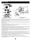
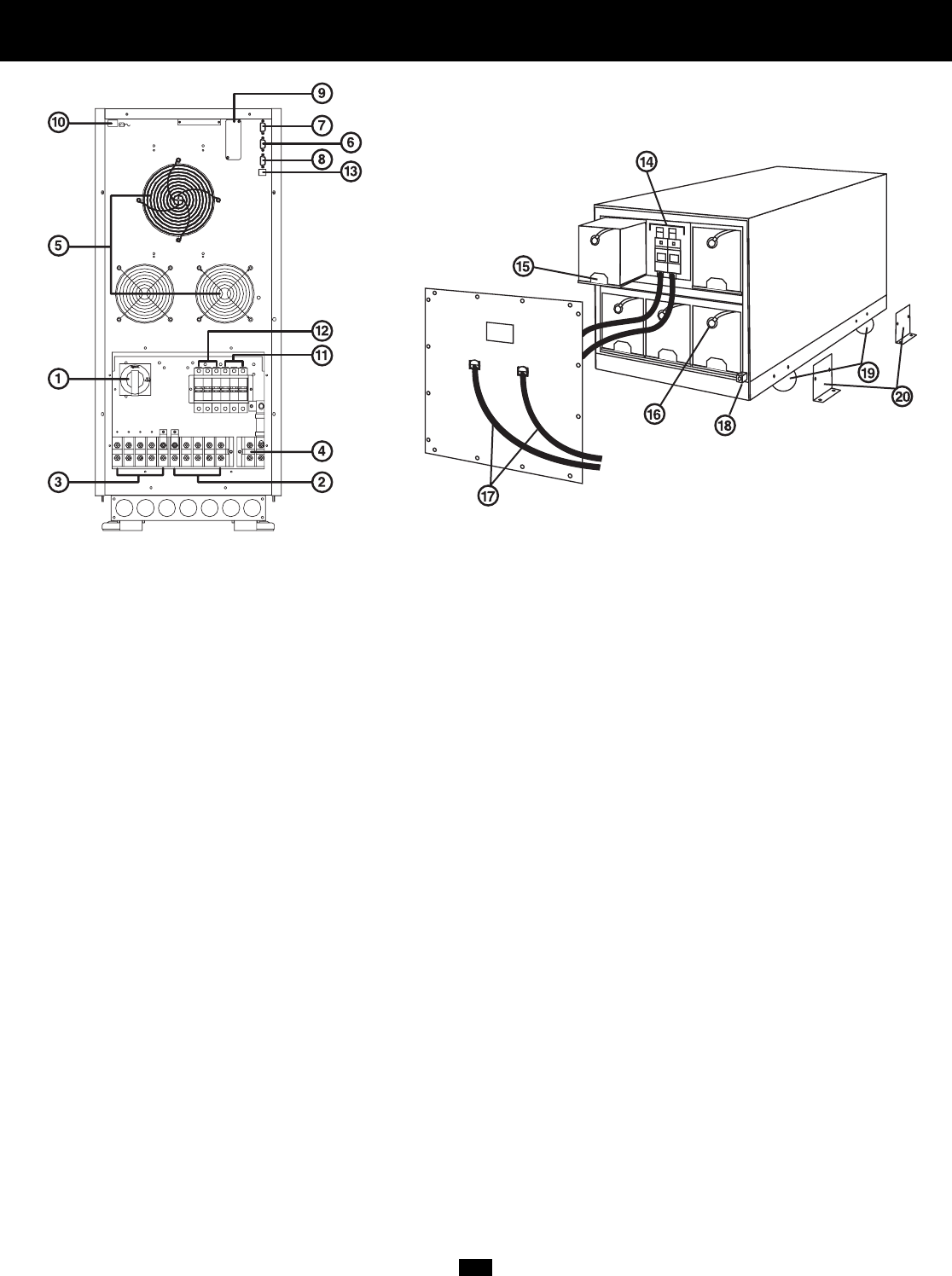
Rear Panels
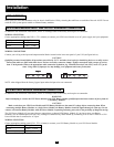
1. Manual Bypass Switch: This dial is used in one step of putting the UPS in "BYPASS” mode, which must be done before performing
any maintenance on the UPS with the connected load supported. [See “Operation (Special Conditions)” for step-by-step instructions for
going into “BYPASS.”] While this switch is on “BYPASS,” connected equipment will receive filtered AC mains power, but will not receive
battery power in the event of a blackout.
2. Input Terminal Block: Use these terminals to connect your UPS to the AC main power input. Unscrew and remove terminal block plate
for access.
3. Output Terminal Block: Use these terminals to connect your UPS to equipment. A plate covering the terminal block must be unscrewed
and removed for access.
4. External Battery Terminal Block: Use this to connect a Tripp Lite battery module to the power module. Remove the cover for access.
The power module will not start without a connection to a charged battery module.
5. Exhaust Fans: These cool and ventilate the inside of the UPS.
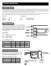
6. AS-400 Interface Port: This female DB9 port connects your UPS to an IBM AS-400 computer interface via the AS-400 Cable includ-
ed. It uses AS-400 communications to report UPS status and power conditions. Using this port, an IBM AS-400 computer can automati-
cally save open files and shut down its operating system during a blackout. See “Communications” for details.
7. “Smart” RS-232 Interface Port: This female DB9 port connects your UPS to a workstation or server. It uses RS-232 communications
to report UPS and power conditions. It is used with Tripp Lite software and the included RS-232 Cable to monitor and manage network
power and to automatically save open files and shut down equipment during a blackout. See “Communications” for details.
8. Dry Contact Interface Port: This female DB9 port sends contact-closure signals to indicate line-fail and low-battery status. See
“Communications,” for details.
9. Accessory Slot: Remove the small cover panel and use optional accessories to remotely control and monitor your UPS. Contact Tripp
Lite Customer Support for more information and a list of available SNMP, network management and connectivity products.
10. “Battery Start” Switch: This momentary rocker switch allows you to “cold-start” your UPS and use it as a stand-alone power source
when utility-supplied AC power is not present. The switch enables the UPS’s DC/AC Inverter. Before “cold-starting” your UPS, make sure
your power module and external battery module(s) are properly installed. Press and hold the “Battery Start” Switch and then press the “ON”
button to turn your UPS ON. To turn it OFF after “cold-start,” press the “OFF” button.
11. AC Input Switch: One triple-pole circuit breaker controls input power to the UPS during normal operation.
12. Bypass AC Input Switch: One triple-pole circuit breaker controls input power to the UPS during “BYPASS” operation.
13. Remote “Emergency Power OFF” (EPO) Connector: This modular jack allows remote emergency shutdown. See
“Communications” for details.
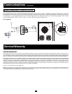
20kVA & 30kVA Battery Module Rear Panel
Model: BP240V33
20kVA and 30kVA Power Modules Rear Panel
Models: SU20K3/3INTPM and SU30K3/3INTPM