


Chapter 2. Hardware Setup
27
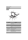
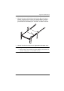
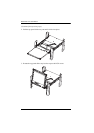
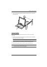
2. While the first person still holds the switch in place, the second person
slides the L brackets into the switch's side mounting brackets, from the
rear until the bracket flanges contact the rack, then – using the screws
provided with the rack mounting kit – screws the L brackets to the rack.
3. After the L brackets have been secured, tighten the front bracket screws.
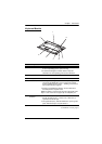
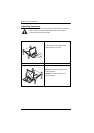
Note: 1. Cage nuts are provided for racks that are not prethreaded.
2. Allow at least 2” on each side for proper ventilation, and at least 5” at
the back for the power cord and cable clearance.