


4
1
5
9
3
7
11
2
6
10
4
8
12
13
14
2 – Important Safety Instructions
SAVE THESE INSTRUCTIONS
All sections of this manual contains instructions and warnings that should be followed during the installation and operation of the UPS
systems described in this manual. Read all instructions thoroughly before attempting to move, install or operate the UPS systems described in
this manual. Failure to comply may invalidate the warranty and cause property damage and/or personal injury.
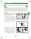
Location Warnings
Install the UPS system in a controlled indoor environment, away from moisture, temperature extremes, flammable liquids and gasses, conductive •
contaminants, dust and direct sunlight.
Install the UPS system in a • level, structurally sound location.
The UPS system is extremely heavy; be extremely careful when moving or lifting the unit.•
Operate the UPS system at indoor temperatures between 32° F and 104° F (0° C and 40° C) only. For best results, maintain indoor temperatures •
between 62° F and 84° F (17° C and 29° C).
Leave adequate space around all sides of the UPS system for proper ventilation. Do not block, cover or insert objects into the external ventilation •
openings of the cabinet.
Do not place any object on the unit, especially containers of liquid.•
Do not mount the unit with its front or rear panel facing down (at any angle). Mounting in this manner will seriously inhibit the unit’s internal •
cooling, eventually causing product damage not covered under warranty.
Do not install the UPS system near magnetic storage media, as this may result in data corruption. Keep all recorded magnetic media a minimum •
of 60 cm (24 inches) away from the UPS system.
Do not attempt to stack the UPS system. Attempting to stack the UPS system may cause permanent damage and create a potential for serious •
personal injury.
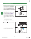
The casters are designed for minor position adjustments within the final installation area only. The casters are not designed for moving the UPS •
system over longer distances.
The casters are not designed to provide long-term support for the UPS system after final installation. Use the levelers to provide long-term •
support.
When moving the UPS system, push from the front or rear, not from the sides.•
Do not attempt to unpack or move the UPS system without assistance.•
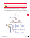
Connection Warnings
The UPS system must be installed in accordance with the requirements of IEC 60364-4-48. Compliance with the following standards •
is required: EN 50091-1-1, EN 50091-2 Class A, IEC 61000-4-2 Level 4, IEC 61000-4-3 Level 3, IEC 61000-4-4 Level 4, IEC 61000-4-5
Level 4, IEC 61000-4-6.
The UPS system contains hazardous high voltages that have the potential to cause personal injury or death from electric shock.•
The UPS system has its own energy source (battery – internal and/or external). The output terminals may be live even when the UPS system is •
not connected to an AC supply.
The power supply for the UPS system must be 3-phase rated in accordance with the equipment nameplate.•
The power supply for the UPS system must be suitably grounded according to all applicable electrical wiring regulations.•
If the UPS system receives power from a motor-powered AC generator, the generator must provide clean, filtered, computer-grade output.•
Use of this equipment in life support applications where failure of this equipment can reasonably be expected to cause the failure of the life •
support equipment or to significantly affect its safety or effectiveness is not recommended. Do not use this equipment in the presence of a
flammable anesthetic mixture with air, oxygen or nitrous oxide.
The UPS system is designed to power modern computer loads and associated peripheral devices. Do not use the UPS system to power pure •
inductive or capacitive loads.
Input and output wiring should be performed by trained, qualified electricians only.•
Due to high leakage current, a proper earth ground connection is essential before connecting the AC supply.•
Isolate the UPS system before working on the circuit. An easily accessible disconnect device should be incorporated in the fixed wiring. The •
disconnect device must be a 4-pole device and must disconnect all line conductors and the neutral conductor.
200706017 93-2688 SU manual 4C.indd 4200706017 93-2688 SU manual 4C.indd 4 11/29/2007 2:02:17 PM11/29/2007 2:02:17 PM